Bipolar optical connector

a technology of optical connectors and sockets, applied in the direction of optical elements, coupling device connections, instruments, etc., can solve the problem of additional and achieve the effect of reducing the danger of optical fiber mix-up

Inactive Publication Date: 2006-10-31
LEOPOLD KOSTAL GMBH & CO KG
View PDF14 Cites 26 Cited by
  • Summary
  • Abstract
  • Description
  • Claims
  • Application Information

AI Technical Summary

Benefits of technology

[0008]A bipolar optical plug-and-socket connector in accordance with the present invention is advantageous over the presented prior art in that in a preassembled condition both ends of the optical fibers already have housing parts on them. The housing parts protect the sensitive end surfaces of the optical fibers without requiring additional measures and minimize the danger of an optical fiber mix-up.
[0010]Thus, each individual optical fiber can be preassembled with each of its two ends already inserted into one of the two different housing portions. Each housing portion includes preliminary means for locking the inserted fiber end sleeve into the housing portion. The locking motion provided by the preliminary means is done from behind the inserted fiber end sleeve in the plugging direction. This locking motion provides security for transport of the individual optical fibers inserted into and covered by the respective housing portions.

Problems solved by technology

Performing the final assembly at the time when the ring line is being put together presents an additional danger of optical fiber mix-up.

Method used


Image

  • Bipolar optical connector
  • Bipolar optical connector
  • Bipolar optical connector

Examples


Embodiment Construction

)

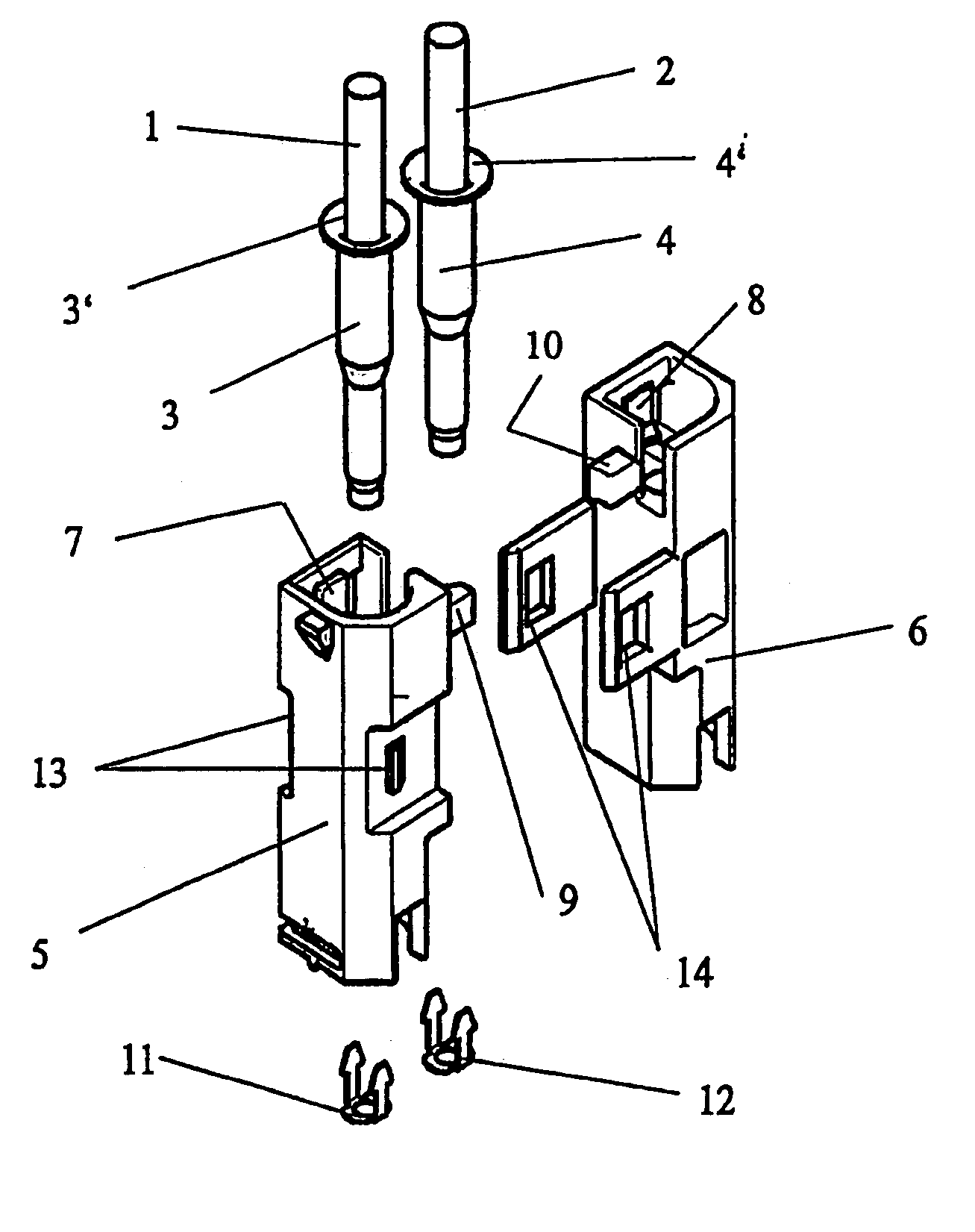
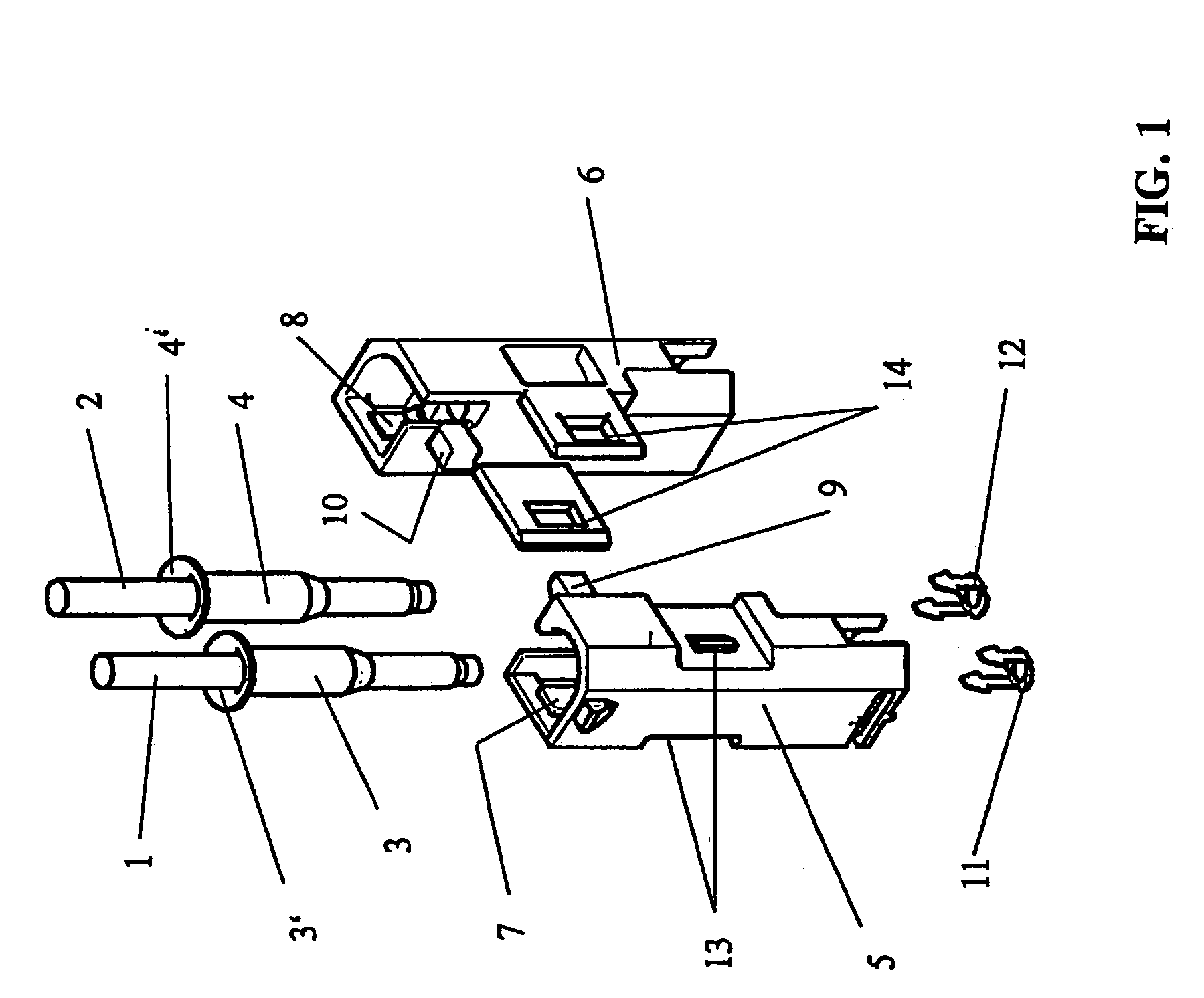
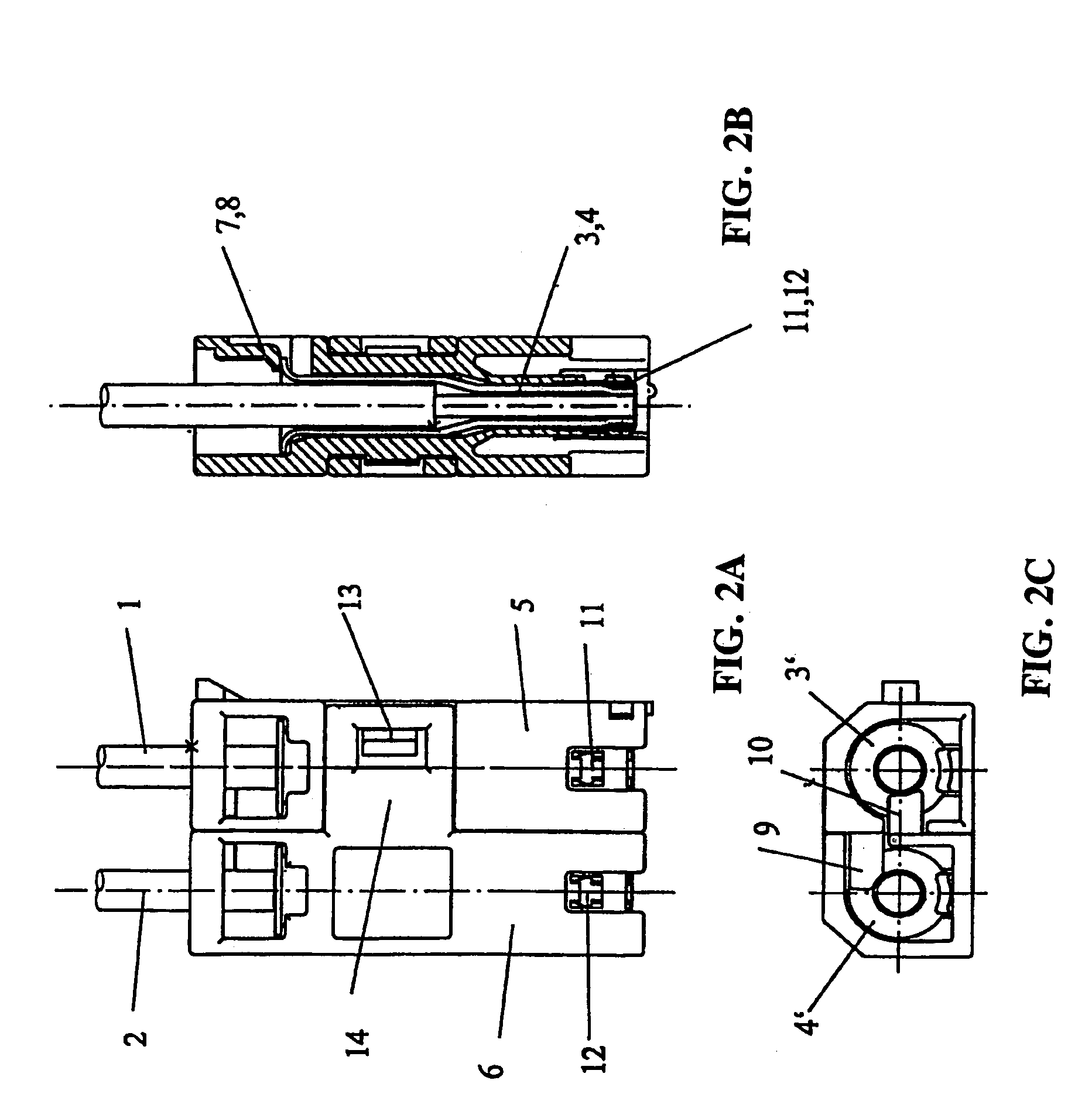
[0019]As shown in the FIGS., a bipolar optical plug-and-socket connector in accordance with the present invention includes a first housing portion or half 5 and a second housing portion or half 6. First and second housing portions 5, 6 have different external physical forms from one another. That is, first and second housing portions 5, 6 are of different types from one another. First and second housing portions 5, 6 are operable to receive respective fiber end sleeves 3, 4. Fiber end sleeves 3, 4 terminate respective optical fibers 1, 2. As such, first and second housing portions 5, 6 receive the terminated ends of optical fibers 1, 2 upon the fiber end sleeves being inserted into the housing portions.

[0020]When optical fiber 1 is preassembled with an end terminated in fiber end sleeve 3, fiber end sleeve 3 inserts into first housing portion 5 to provide the first housing portion with optical fiber 1. Fiber end sleeve 3 inserts into first housing portion 5 from behind along a plug...


PUM


Abstract

A bipolar optical plug-and-socket connector for connecting two optical fibers with other optical fibers and electro-optical transmission and receiving devices includes an optical housing for holding two fiber end sleeves in which each sleeve terminates a fiber. The optical housing includes first and second housing portions which have different external forms from one another. The housing portions hold respective ones of the sleeves when the sleeves are inserted into the housing portions along a plugging direction. The housing portions join to one another in a direction running perpendicular to the plugging direction to place the optical housing in a fully assembled position while the housing portions hold the sleeves. Each housing portion includes an end lock for locking the sleeves in the housing portions. The end locks of the housing portions lock the sleeve held in the other of the housing portions when the housing portions are joined together.

Description

CROSS-REFERENCE TO RELATED APPLICATIONS[0001]This is a continuation of International Application PCT / EP2003 / 006424, published in German, with an international filing date of Jun. 18, 2003, which claims priority to DE 102 28 008.8 filed Jun. 22, 2002, which are both hereby incorporated by reference.BACKGROUND OF THE INVENTION[0002]1. Field of the Invention[0003]The present invention generally relates to a bipolar optical plug-and-socket connector for connecting two optical fibers with other optical fibers, electro-optical transmission devices, or electro-optical receiving devices in which the bipolar optical connector has an optical housing for holding two fiber end sleeves which terminate respective ends of the two optical fibers.[0004]2. Background Art[0005]Optical plug-and-socket connectors connect optical fibers with one another and to devices having opto-electronic transducers. Optical fibers are used to build so-called ring bus structures which are especially prevalent in autom...

Claims


Application Information

Patent Timeline
Patent Type & Authority Patents(United States)
IPC IPC(8): G02B6/38H01R13/627G02B6/36
CPCG02B6/3869G02B6/3873G02B6/3878G02B6/3879
Inventor SCHERER, THOMASMOHS, WOLFGANGHERINGHAUS, WILFRIED
Owner LEOPOLD KOSTAL GMBH & CO KG
Why Eureka
Try Eureka