
Electrical connector with locking/unlocking means

a technology of locking/unlocking means and electrical connectors, applied in the direction of coupling device connections, coupling parts engagement/disengagement, electrical apparatus, etc., can solve the problems of easy damage to the structure and much harder to pull out complementary connectors, so as to reduce the exertion of force

Inactive Publication Date: 2006-10-31
HON HAI PRECISION IND CO LTD
View PDF6 Cites 45 Cited by
  • Summary
  • Abstract
  • Description
  • Claims
  • Application Information

AI Technical Summary

Benefits of technology

The present invention provides an electrical connector with locking / unlocking means to reduce the force required to pull out the mating connector and securely lock it. The locking means includes a spring, a moveable member, and a guiding pole that allows for easy engagement and disengagement with the mating connector. The structure is strengthened and durable, making it suitable for long-term use.

Problems solved by technology

The structure is easy to be damaged when an excessive force is exerted thereon for pulling the plug 40 out of the jack 15.
The connector has a longer mating portion compared to the conventional connector and thus, it is much harder to pull a complementary connector out due to the long length of the mating portion thereof.

Method used


Image

  • Electrical connector with locking/unlocking means
  • Electrical connector with locking/unlocking means
  • Electrical connector with locking/unlocking means

Examples


Embodiment Construction

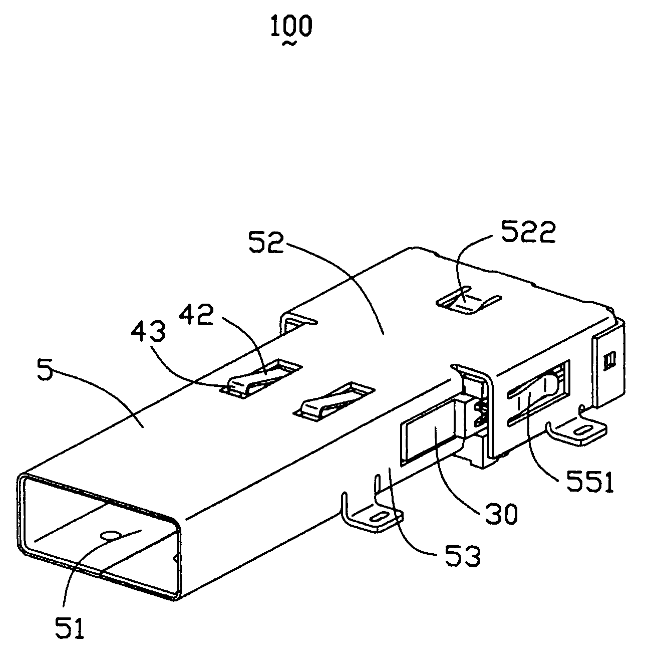
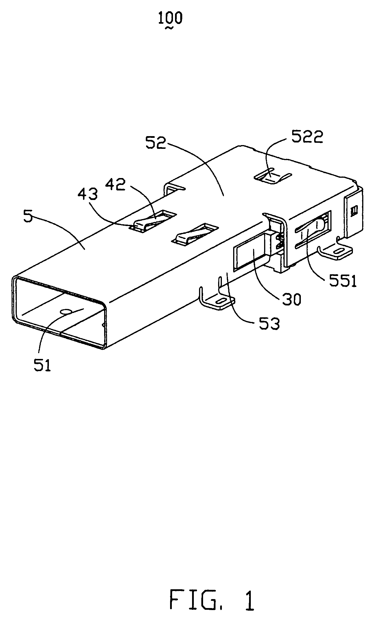
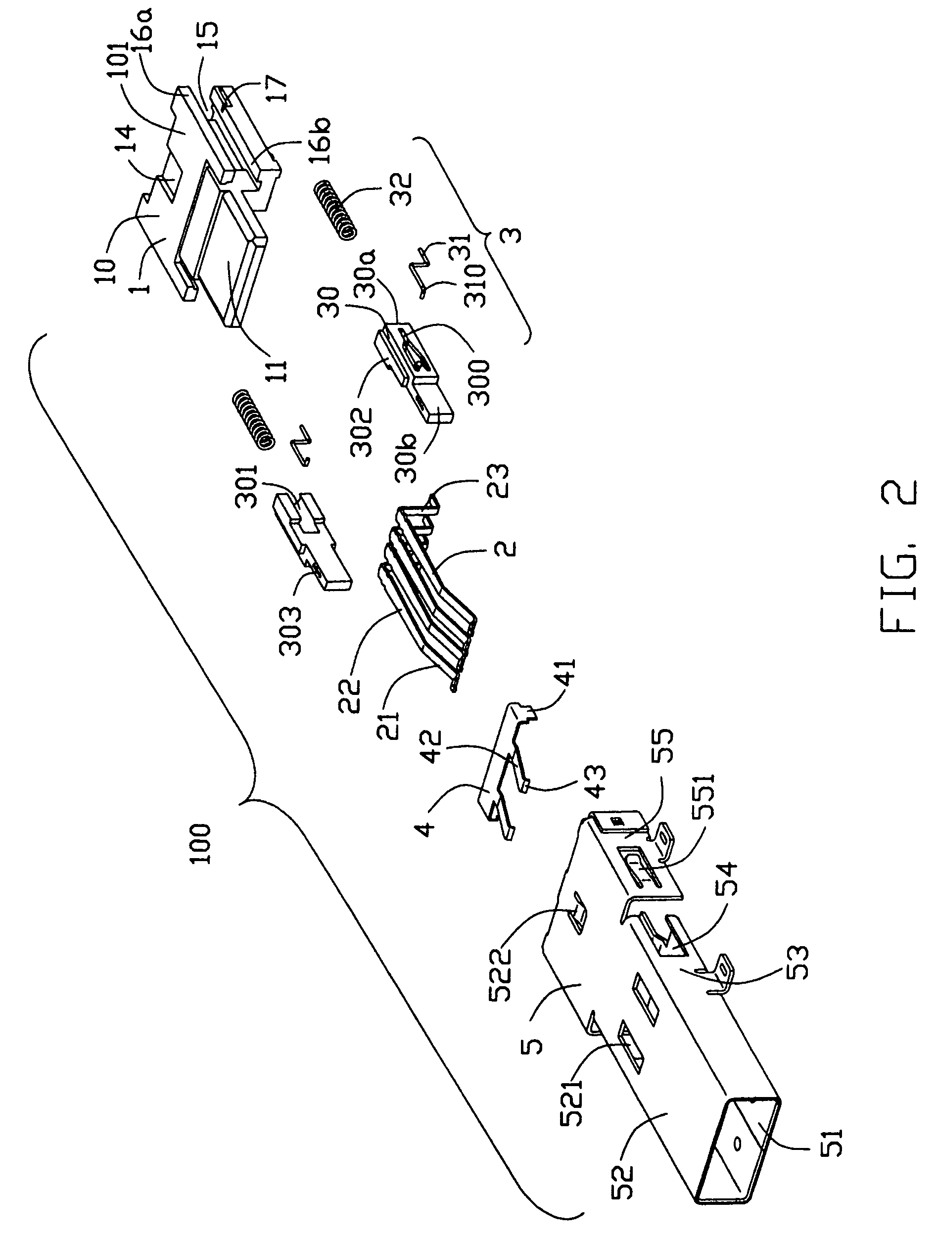
[0020]Referring to FIGS. 1–3, an electrical connector 100 in accordance with the present invention, which is a USB connector in this exemplary embodiment, comprises an insulative housing 1, a plurality of terminals 2, a pair of locking / unlocking means 3 or a push-push means, a latch 4 and a metal shell 5.

[0021]The insulative housing 1 comprises a body portion 10 and a rectangular nose portion 11 extending forwardly from the body portion 10. The body portion 10 comprises a top face 101, an opposite bottom face 102, a pair of upper flanges 16a protruding laterally from opposite sides of the top face 101, and a pair of lower flanges 16b extending laterally from opposite sides of the bottom face 102. The body portion 10 also has a pair of grooves 15 defined between corresponding upper and lower flanges 16a, 16b for retaining the locking / unlocking means 3. The grooves 15 extend in a longitudinal direction throughout a front surface to a rear surface (not labeled) of the body portion 10. ...


PUM


Abstract

An electrical connector (100) adapted for mating with a complementary connector (6), includes an insulative housing (1) defining a number of channels (12) and grooves (15), a number of terminals (2) received in the channels, a pair of locking / unlocking means (3) retained in the grooves, a latch cooperating with locking / unlocking means for engaging / disengaging with the complementary connector and a metal shell (5). The locking / unlocking means includes a spring (32), a moveable member (30) defining a guiding slot (300) and a guiding pole (31) slidable in the guiding slot by exerting twice push operations, the complementary connector can be engaged with and disengaged from the connector due to displacement of the guiding pole in the guiding slot.

Description

BACKGROUND OF THE INVENTION[0001]1. Field of the Invention[0002]The present invention relates to an electrical connector, and particularly to a USB connector with locking / unlocking means for detachably mating with a complementary connector.[0003]2. Description of Related Art[0004]A conventional USB (Universal Serial Bus) connector for mating with a mating connector is described in U.S. Pat. No. 6,902,432. The USB connector 10 comprises a jack 15 mating with a plug 40. The jack 15 comprises a shield shell 16 and a plurality of jack terminals 35 mounted in the shield shell 16. The plug 40 includes a shield case 41 and a plurality of plug terminals fitted into the shield shell 16 for electrically connecting with the jack terminals 35. The shield shell comprises an upper wall 16a, a tongue piece 18 protruding downwardly from the upper wall 16a, and a pair of contact portions 19 symmetrically formed on both sides of the tongue piece 18. A U-shaped groove 20 is defined by punching along a...

Claims


Application Information

Patent Timeline
Patent Type & Authority Patents(United States)
IPC IPC(8): H01R13/62
CPCH01R13/6275H01R13/635H01R13/641H01R13/6582
Inventor HU, JIN-KUIZHANG, GUO-HUAZHU, ZI-QIANG
Owner HON HAI PRECISION IND CO LTD
Learn More