Removable vent having a filter for use in a building foundation

a filter and venting technology, applied in ventilation systems, heating types, separation processes, etc., can solve the problem that the spring clips cannot provide resistance, and achieve the effect of easy removal of the ventilating uni

Inactive Publication Date: 2006-10-31
A I AIR TECH
View PDF18 Cites 37 Cited by
  • Summary
  • Abstract
  • Description
  • Claims
  • Application Information

AI Technical Summary

Benefits of technology

[0007]The present invention is a ventilating unit dimensioned, for example, to replace one concrete block in the wall of a crawlspace beneath a house. However, this ventilating unit can also be used in any kind of foundation whether or not the foundation consists of separate blocks or bricks, as opposed to a continuous material. During insertion of the unit, depressible pieces (e.g. spring clips) at the unit's periphery are depressed in order to hold the unit in place. However, the unit includes at least one manual handling feature to easily remove the ventilating unit, while overcoming the resistance of the depressible pieces. The ventilating unit is designed for removal in order to replace a filter that may itself be slidably removable from the unit. The ventilating unit also features an outwardly sloped bottom for drainage of liquids, for example due to condensation.
[0008]The filter is for filtering out 90% or more of the active outdoor mold spores. This filter will need to be replaced periodically, and therefore the spring clips are positioned near the front of the ventilating unit, so that the spring clips will not provide resistance after the ventilator unit is removed a small distance from its installed position.
[0009]The front of the ventilator faces away from the building when the ventilator is installed, and the rear of the ventilator faces into the building when the ventilator is installed. A securing device such as a set of brackets may be located at the rear of the ventilator, for securing the air filter to the rear of the ventilator. At least one of the manual handling features (e.g. a handle or hand grab), located at the front of the ventilator, is for removing the ventilator from between the concrete blocks. No tools are required to install or remove the vent, so a typical homeowner will be able to maintain a dry, clean crawlspace without difficulty. When installed, the front of the ventilator may advantageously have edges that are separated from the building foundation by a gasket of foam or rubber, in order to further protect the inside of the building from unwanted spores, moisture, insects, and the like.

Problems solved by technology

This filter will need to be replaced periodically, and therefore the spring clips are positioned near the front of the ventilating unit, so that the spring clips will not provide resistance after the ventilator unit is removed a small distance from its installed position.

Method used


Image

  • Removable vent having a filter for use in a building foundation
  • Removable vent having a filter for use in a building foundation
  • Removable vent having a filter for use in a building foundation

Examples


Embodiment Construction

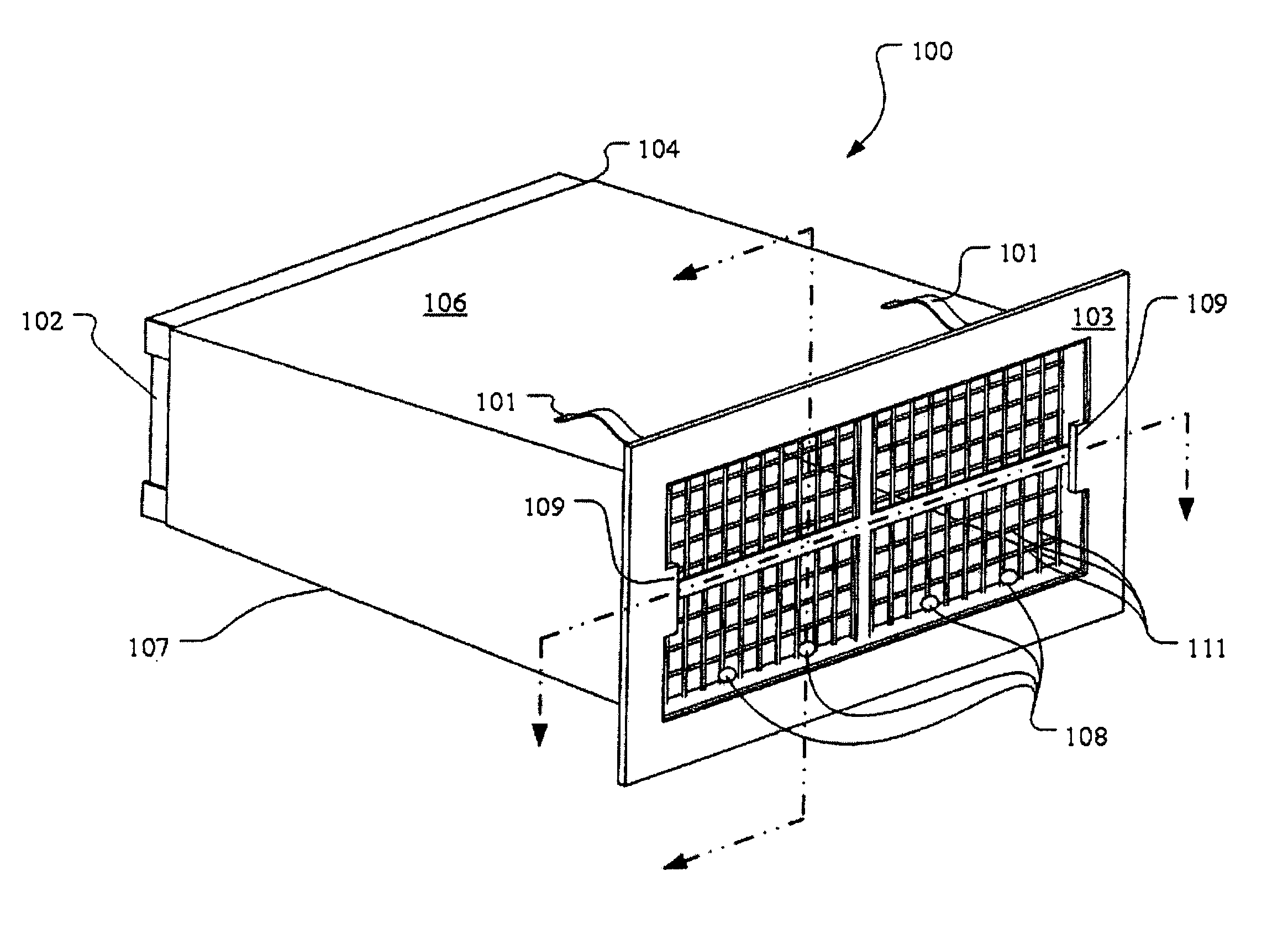
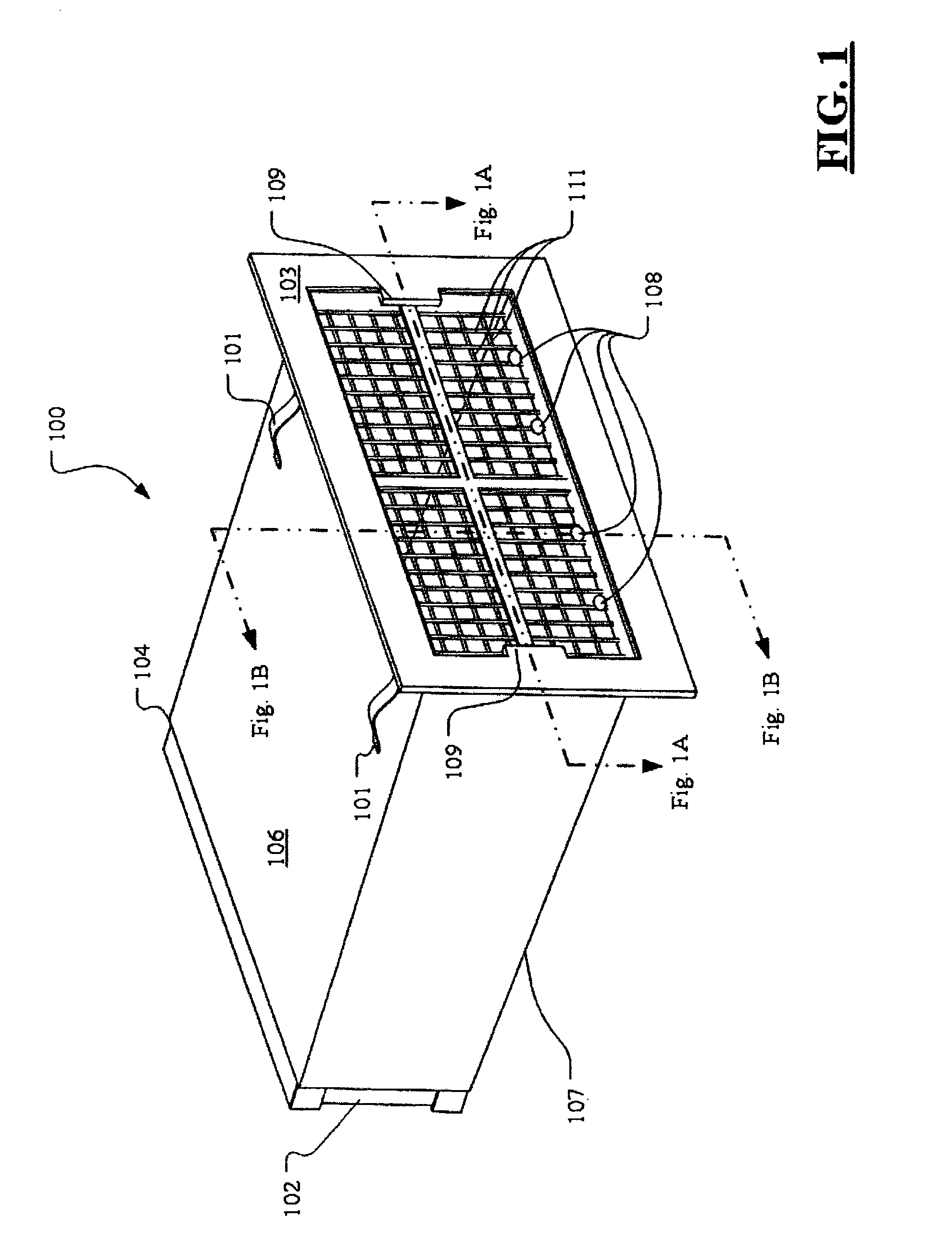
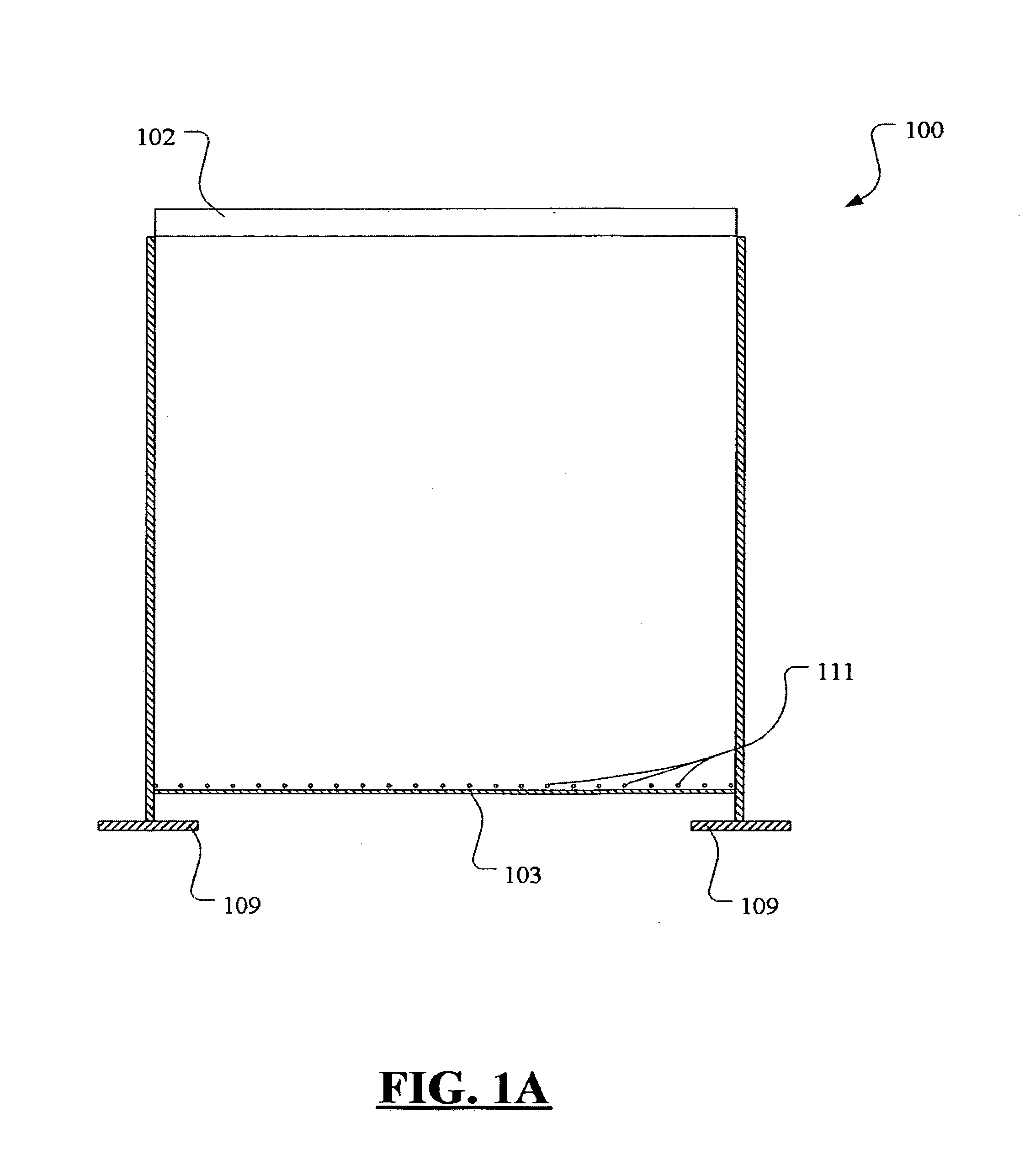
[0019]A best mode embodiment of the present invention can be best appreciated by reference to the accompanying drawings. As seen in FIG. 1, the ventilator 100 is preferably formed of hard plastic or rustproofed metal, and is equipped to hold a preferably replaceable air filter 102, the ventilator being dimensioned for placement between concrete blocks in a building foundation. The front 103 of the ventilator faces away from the building when the ventilator is installed. The rear 104 of the ventilator faces into the building when the ventilator is installed.

[0020]The ventilator includes a ceiling 106, and a floor 107. The ceiling is substantially flat and the floor is substantially flat also. The ceiling and the floor are at an angle to each other so that the floor and ceiling are farther apart at the front than at the rear, and thus the floor is sloped to allow moisture such as rain to exit through at least one drainage area, such as the drain holes 108 at the front 103 of the venti...


PUM

PropertyMeasurementUnit
sizeaaaaaaaaaa
angleaaaaaaaaaa
angleaaaaaaaaaa

Abstract

A removable ventilator is equipped to hold an air filter, the ventilator being designed for placement in a building foundation, for example between concrete blocks. The front of the ventilator faces away from the building when the ventilator is installed. The rear of the ventilator faces into the building when the ventilator is installed. At least one securing device is located at the rear of the ventilator, for securing the air filter to the rear. At least one manual handling feature is located at the front of the ventilator, for removing the ventilator from between the concrete blocks.

Description

TECHNICAL FIELD [0001]The present invention relates to spaces beneath buildings, and more particularly to ventilation for those spaces.BACKGROUND OF THE INVENTION [0002]Ventilators for basements and crawlspaces are known in the art, including ventilators that are held in place by spring clips. See, for example, Sarazen (U.S. Pat. No. 4,669,371). However, such ventilating units do not eliminate the problem of mold and other organic growth in the crawlspace, and in fact can exacerbate the problem by allowing access of such organic material into the crawlspace.[0003]Rain, humidity, mold, and pollen often find their way into existing ventilators, and thence into the basement or crawlspace. If one of the existing ventilators were to be equipped with a filter, the filter would be subject to moisture, making it soggy, and in fact creating a potential breeding place for mold, and the filter would not be easily replaced, and may require professional replacement using tools of the trade.[0004...

Claims


Application Information

Patent Timeline
Patent Type & Authority Patents(United States)
IPC IPC(8): F24F13/28E04B1/70F24F7/00F24F13/08
CPCE04B1/7076F24F13/085F24F2007/0025
Inventor BELIVEAU, JOHN A.BUONAIUTO, SR., FRANK V.BUONAIUTO, ANTHONY B.
Owner A I AIR TECH
Why Eureka
Try Eureka