Redundant imaging systems

a technology of imaging system and image, applied in the field of image array and method, can solve the problems of deformation of the image, and affecting the quality of the result, and achieve the effect of reducing the quality of the resul

Inactive Publication Date: 2006-10-31
APTINA IMAGING CORP
View PDF16 Cites 133 Cited by
  • Summary
  • Abstract
  • Description
  • Claims
  • Application Information

AI Technical Summary

Problems solved by technology

One problem with conventional imaging arrays concerns defective or malfunctioning photodetectors.
Defective photodetectors typically result in erroneous image signals that ultimately degrade the quality of resulting images.
One limited solution to this problem has been to identify the defective photodetector and to generate a substitute image signal for the image signal of the defective photodetector, with the substitute image signal based on an average of the image signals from detectors surrounding it.
However, this solution suffers from the disadvantage that the substitute image signal introduces artifacts into the resulting image.

Method used


Image

  • Redundant imaging systems
  • Redundant imaging systems
  • Redundant imaging systems

Examples


Embodiment Construction

[0013]The following detailed description, which references and incorporates FIGS. 1–3, describes and illustrates one or more specific embodiments of the invention. These embodiments, offered not to limit but only to exemplify and teach, are shown and described in sufficient detail to enable those skilled in the art to implement or practice the invention. Thus, where appropriate to avoid obscuring the invention, the description may omit certain information known to those of skill in the art.

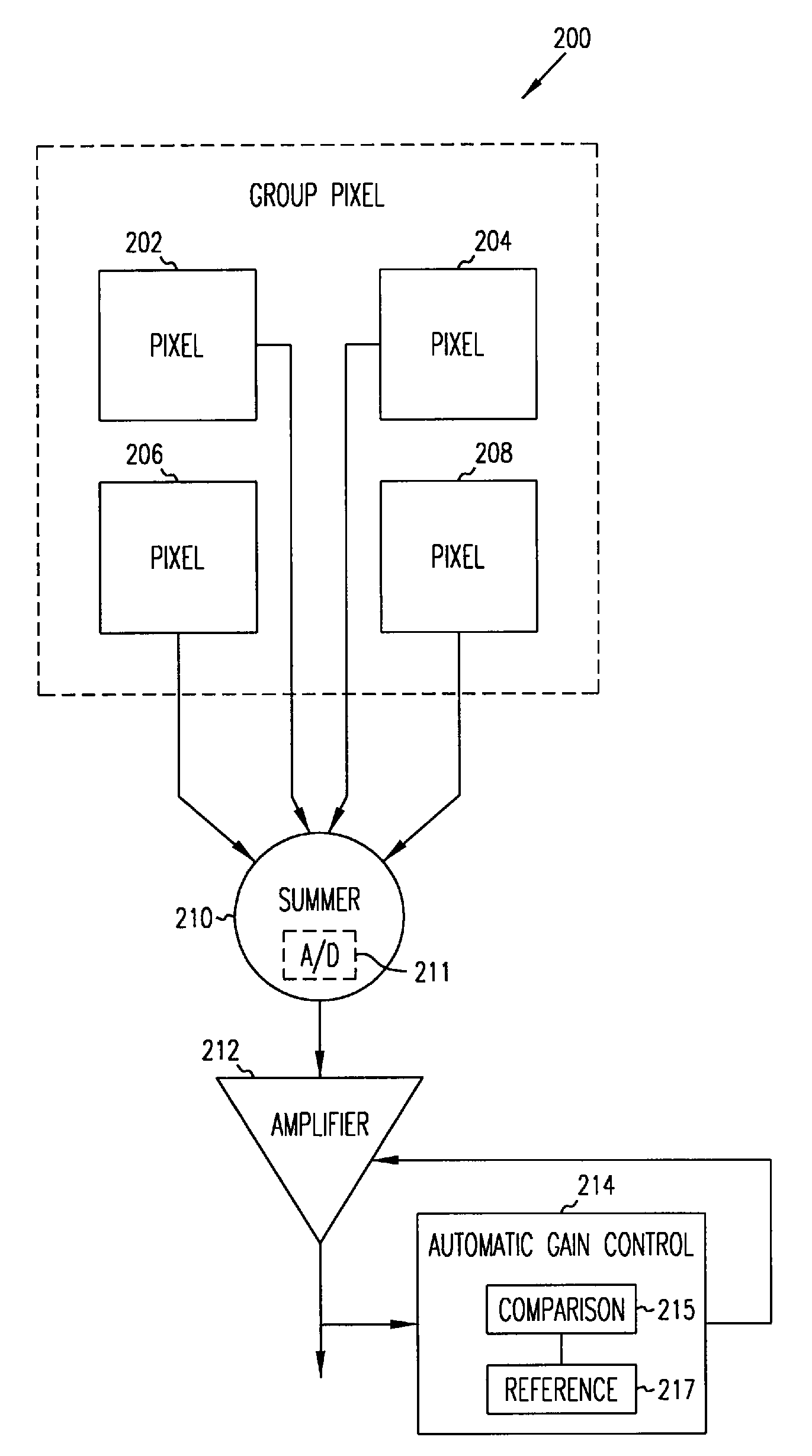
[0014]FIG. 1 shows an exemplary imaging array 100 incorporating teachings of the present invention. Imaging array 100 includes group pixels 110, 112, 114, and 116, an address line 120, a drain line 130, a reset line 140, and a signal line 150. for controlling the group pixels. (For clarity, the figure omits conventional features, such as row-select logic, column-select logic, timing-and-control circuitry, and analog-to-digital converters.) In the exemplary embodiment, array 100 includes four group...


PUM


Abstract

Imaging arrays typically include thousands or millions of photodetectors that convert sensed light into corresponding electric signals, which are ultimately converted into digital image signals for recording or viewing. One problem with conventional imaging arrays concerns faulty photodetectors, which produce erroneous image signals that ultimately degrade the quality of resulting images. Accordingly, the present inventors devised new imaging arrays including redundant photodetectors to compensate for faulty ones. One exemplary embodiment includes photodetectors that are substantially smaller than conventional photodetectors and that are arranged into two or more groups, with the photodetectors in each group coupled to produce a single group image signal. If the group image signal for a group falls below some threshold level indicative of a defective or malfunctioning photodetector, the group image signal is amplified to compensate for the loss.

Description

[0001]This application is a Divisional of U.S. application Ser. No. 09 / 650,551, which was filed Aug. 30, 2000, now U.S. Pat. No. 6,756,576 and which is incorporated herein by reference.TECHNICAL FIELD[0002]The present invention concerns imaging arrays and methods, particularly methods for correcting or compensating for defective or malfunctioning photodetectors in an imaging array.BACKGROUND OF THE INVENTION[0003]Imaging arrays are electronic devices that sense light and output electrical signals representative of the sensed light. The imaging arrays are generally coupled to a television screen, computer monitor, or digital camera, which displays or records an image based on the output electrical signals.[0004]An imaging array often includes a rectangular array or matrix of thousands or even millions of photodetectors, with each photodetector having a unique row and column position within the array which corresponds to a particular region, known as a pixel, of a displayed image. Eac...

Claims


Application Information

Patent Timeline
Patent Type & Authority Patents(United States)
IPC IPC(8): H01L21/00H04N9/64H01L27/00H01L27/146H04N5/347H04N5/367H04N5/378
CPCH01L27/14603H01L27/14609H04N5/367H04N25/68
Inventor MCELROY, DAVID J.CLOUD, EUGENE H.
Owner APTINA IMAGING CORP
Why Eureka
Try Eureka