

Optical scanning probe system
a probe system and optical scanning technology, applied in the field of optical scanning probe systems, can solve problems such as difficulty in achieving high resolution
- Summary
- Abstract
- Description
- Claims
- Application Information
AI Technical Summary
Benefits of technology
Problems solved by technology
Method used
Image

Examples
first embodiment
[0080]The optical probe system in the first embodiment of the present invention will now be described through reference to FIGS. 1 to 11.
[0081]In this embodiment, the object is to provide a system with which optical probes of different scanning types can be selectively used so as to obtain an observation image suited to the examination site.
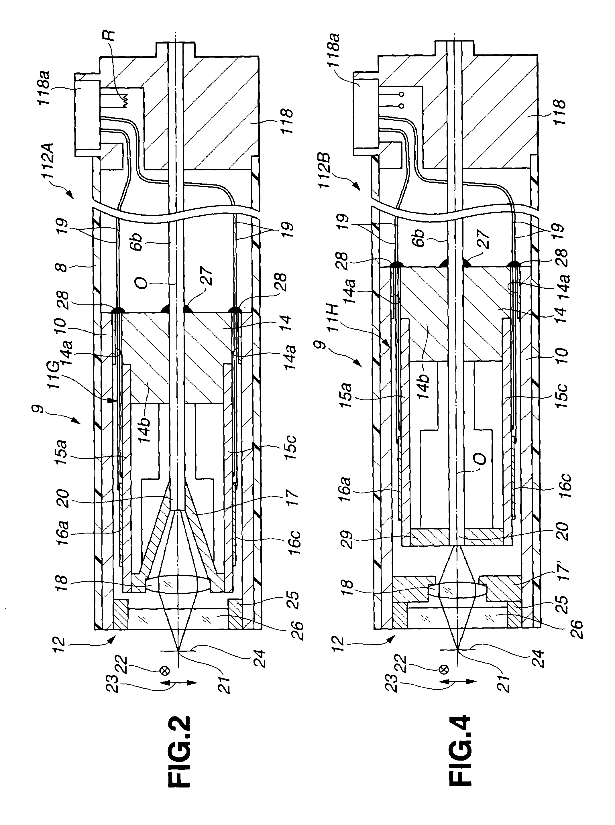
[0082]In specific terms, when an organ near the heart is to be observed, for instance, an observation image that is not greatly affected by the movement of the heart (that is, one with little blurring) can be obtained by using an optical fiber scanning type of optical probe which affords higher scanning speed. When an organ that is distant from the heart and therefore moves very little is to be observed, an image of higher resolution can be obtained by using an optical fiber and lens scanning type of optical probe.
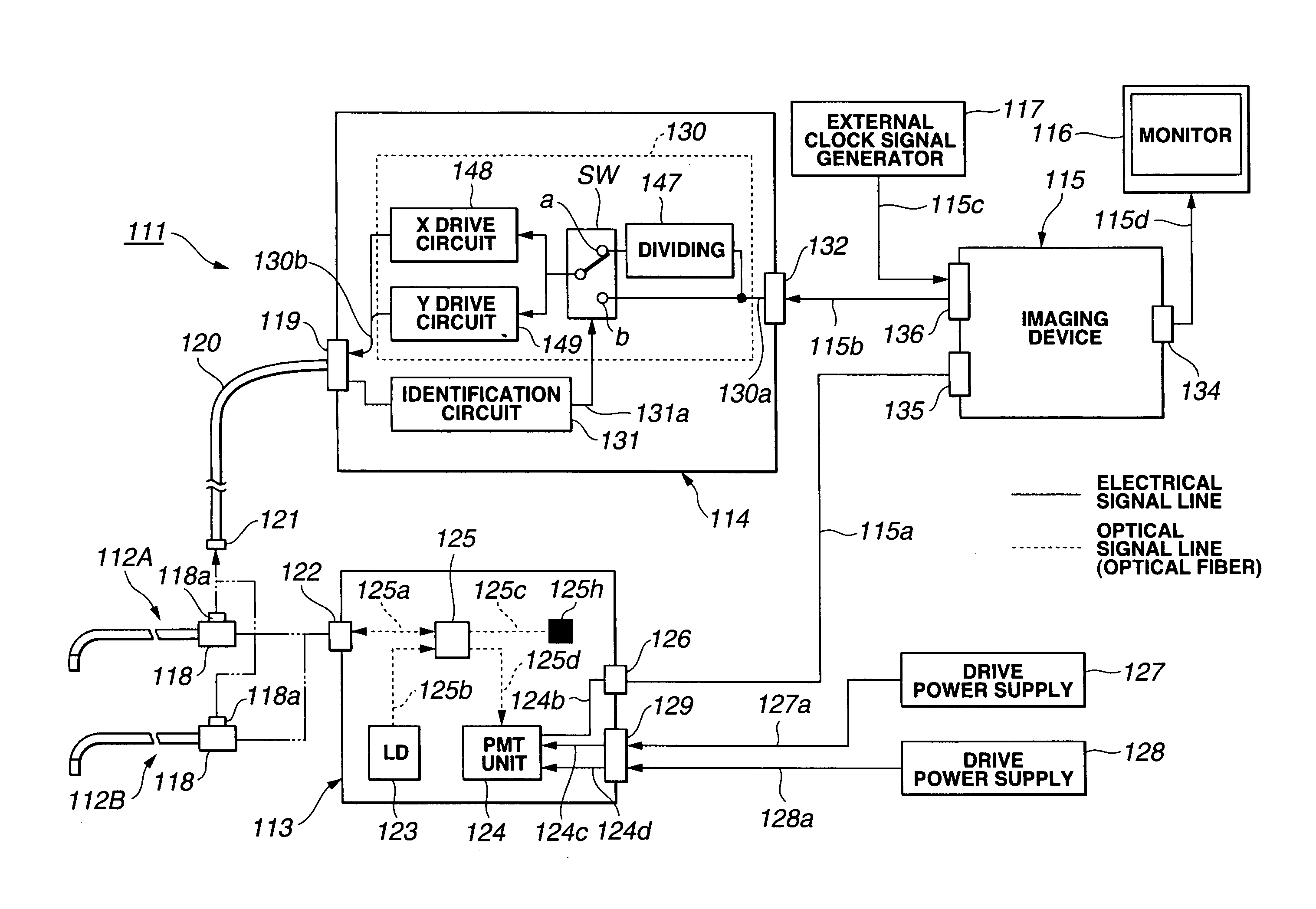
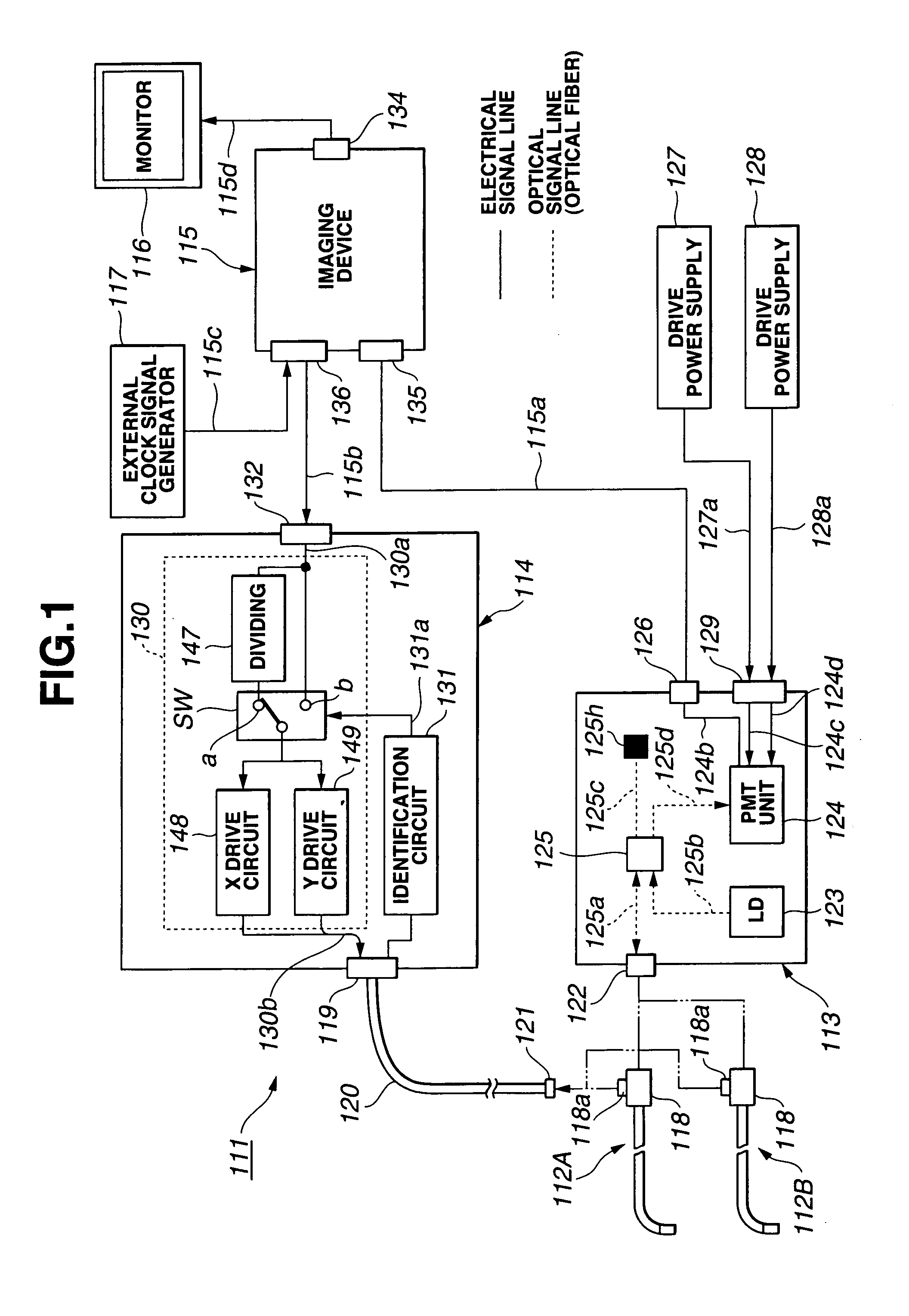
[0083]The optical probe system 111 shown in FIG. 1 comprises an optical fiber and object lens integrated scanning type of optical prob...
second embodiment
[0180]A second embodiment of the present invention will now be described through reference to FIGS. 12A to 19. It is an object of this embodiment to provide an optical probe that is simple to assemble and therefore lower in cost, and with which the effect of interference due to resonance can be reduced.
[0181]FIG. 12A is an exploded view (prior to assembly) of a drive unit 161 and a support member 162 that is attached to the rear of this drive unit 161. This drive unit 161 is provided with a slit 163d, wherein a rectangular bottom plate 163a and side plate 163b are formed from a single piece of spring material such as stainless steel (SUS), linked by a small linking component 163c at the rear end.
[0182]Unimorph piezoelectric elements 164a and 164b in the form of rectangular thin plates are affixed to the bottom plate 163a and side plate 163b, respectively. One of the plates, such as the bottom plate 163a, is formed such that its distal end is longer than that of the side plate 163b, ...
third embodiment
[0206]A third embodiment of the present invention will now be described through reference to FIG. 20. It is an object of this embodiment is to provide an optical probe with which a vertical tomogram can be obtained with a simple structure.
[0207]A scanner generally must be driven in the depth direction to obtain a tomogram in the depth direction with an optical probe, but with a scanner that two-dimensionally scans an object lens and an optical fiber, any further drive in the depth direction results in an extremely complicated scanner structure, and the assembly of this scanner is difficult, so in this embodiment a tomogram having a component of the depth direction is obtained with a simple structure as described below.
[0208]The optical probe 201A shown in FIG. 20 is like the optical probe 112A in FIG. 2, but a prism 202 for changing the optical path to the side at a right angle is disposed ahead of the emission end 20 of the optical fiber 6b, and the light emitted in the lengthwise ...
PUM
 Abstract
Description
Claims
Application Information