Apparatus for controlling articles in custody

Inactive Publication Date: 2006-10-31
UNIREC +1
View PDF19 Cites 55 Cited by
  • Summary
  • Abstract
  • Description
  • Claims
  • Application Information

AI Technical Summary

Benefits of technology

[0006]An object of the present invention is to provide an apparatus for controlling articles in custody, capable of enabling a plurality of persons to open and close a safe at any time and securely controlling articles in custody.
[0016]In addition to the effects of the first aspect, the second aspect makes the recorder also record a time when the storage unit is unlocked, so that one may easily know when and by whom the storage unit was unlocked. This improves the secure management of the storage unit.
[0018]In addition to the effects of the third aspect, the fourth aspect provides the safe with a lockable safe door and a plurality of inner storage spaces each lockable to keep articles therein and selectively unlockable to allow the articles to be taken out therefrom. The fourth aspect forms the input unit with an outer input unit to input biometric information for unlocking the safe door and an inner input unit to input biometric information for unlocking the inner storage spaces. The selector of the fourth aspect allows an authorized person to select any one of the inner storage spaces to open. The fourth aspect forms the controller with an outer controller to unlock the safe door if the biometric information inputted into the outer input unit is authenticated by collation and an inner controller to unlock the selected inner storage space if the biometric information inputted into the inner input unit is authenticated by collation and if there is the inner storage space selected through the selector.
[0021]In addition to the effects of the first and second aspects, the sixth aspect employs a key storage unit as the storage unit. The key storage unit is lockable to separately keep keys and is selectively unlockable to allow a selected one of the keys to be taken out. Also provided is a key selector to select any one of the keys kept in the key storage unit. The controller selectively unlocks the key storage unit for the selected key if biometric information inputted into the input unit is authenticated by collation and if there is the key selected through the key selector An authorized or registered person inputs his or her biometric information, selects one of the keys in the key storage unit, and takes the selected key out of the key storage unit. According to the sixth aspect, one may easily know which key was taken out by whom and when. Accordingly, the keys are securely managed.

Problems solved by technology

Such remote control has a problem that the safe is unlockable only in response to a command from the remote control center, to force troublesome operations when the safe must frequently be opened and closed by a plurality of persons.

Method used


Image

  • Apparatus for controlling articles in custody
  • Apparatus for controlling articles in custody
  • Apparatus for controlling articles in custody

Examples


first embodiment

(First Embodiment)

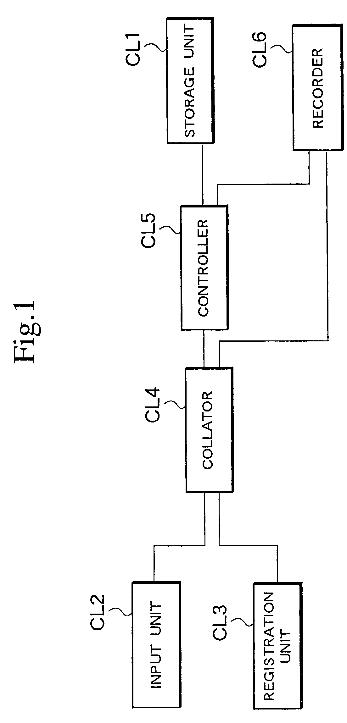
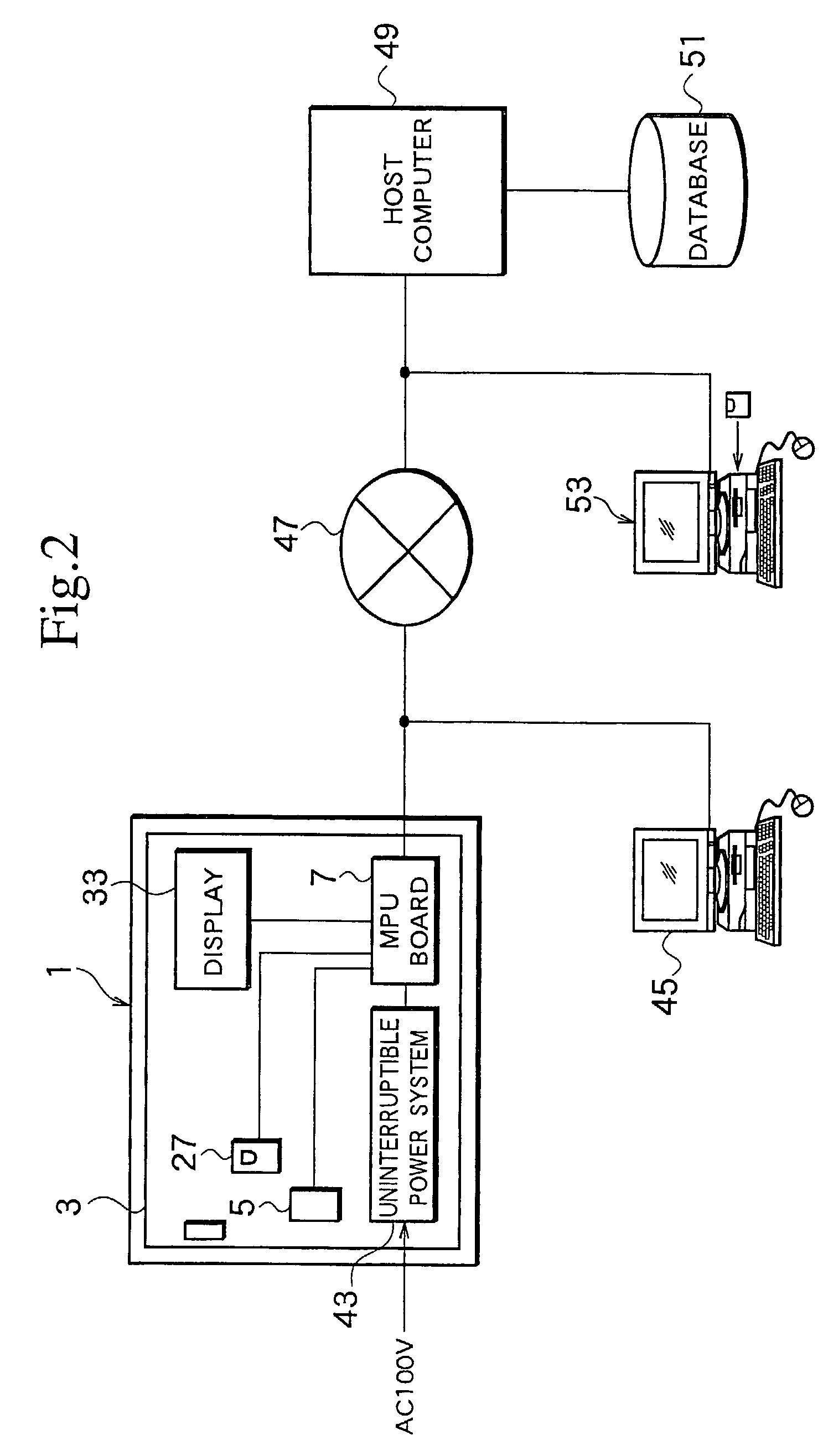
[0039]FIG. 2 is a block diagram showing an apparatus for controlling articles in custody according to a first embodiment of the present invention. A safe 1 in FIG. 2 serves as the storage unit CL1 of FIG. 1. The apparatus of the present invention is applicable to control a plurality of safes arranged in an area or distributed in different areas. The safe 1 has a door 3, which is lockable and unlockable with an electronic lock 5. The lock 5 is connected to an MPU board 7, which sends signals to lock and unlock the lock 5. The MPU board 7 serves as the controller CL5 of FIG. 1.

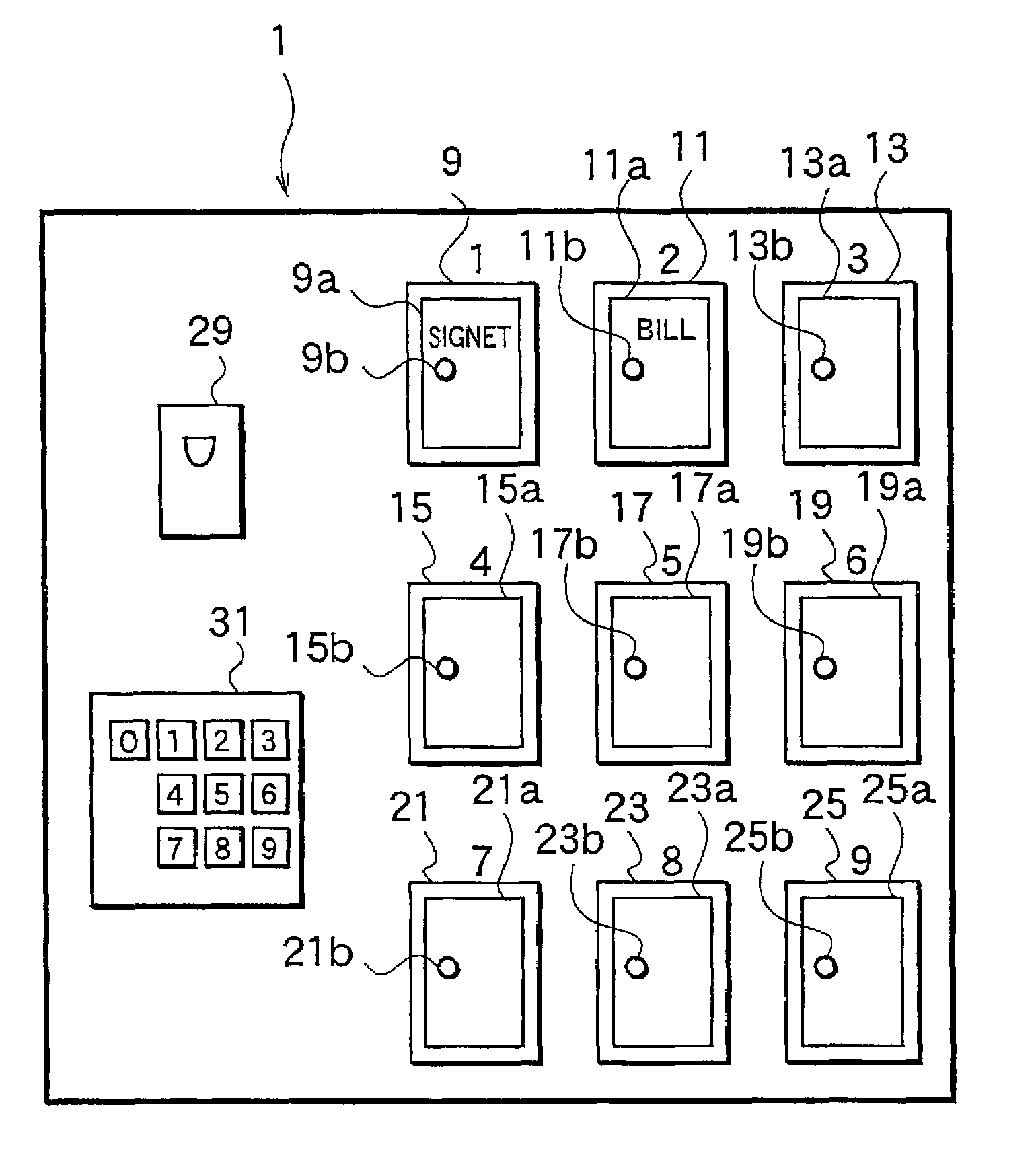
[0040]FIG. 3 shows inner storage spaces 9, 11, 13, 15, 17, 19, 21, 23, and 25 defined in the safe 1. The storage spaces 9 to 25 are visible when the door 3 is opened. The storage spaces 9 to 25 have doors 9a, 11a, 13a, 15a, 17a, 19a, 21a, 23a, and 25a, respectively, which are provided with electronic locks 9b, 11b, 13b, 15b, 17b, 19b, 21b, 23b, and 25b, respectively, to keep articles in the sto...

second embodiment

(Second Embodiment)

[0072]FIGS. 7, 8, and 9 show an apparatus for controlling articles in custody according to the second embodiment of the present invention. The apparatus involves a safe 1 and visually monitors and records the inside state of the safe 1. In FIG. 7, the door of the safe 1 is not shown. According to the second embodiment, the safe 1 has no inner storage spaces and directly stores articles 67 and 69. The safe 1 may have inner storage spaces each provided with a camera to monitor and record the images of articles stored therein.

[0073]The door 3 (not shown) of the safe 1 is constituted like the first embodiment. Namely, the door 3 has an electronic lock 5, an outer input unit 27, and a display 33. The safe 1 has an MPU board 7 connected to the parts 5, 27, and 33 and an uninterruptible power system 43.

[0074]According to the second embodiment, an inner top wall of the safe 1 has a photograph unit such as a CMOS camera 71 and lighting units 73 and 75. The safe 1 has a doo...

third embodiment

(Third Embodiment)

[0086]FIGS. 10 and 11 show an apparatus for controlling articles in custody according to the third embodiment of the present invention, in which FIG. 10 is a front view showing a storage unit according to the third embodiment and FIG. 11 is a flowchart showing an operation according to the third embodiment. According to the third embodiment, a key storage unit 83 serves as the storage unit CL1 of FIG. 1 to control keys 77, 79, and 81. Although the number of the keys in FIG. 10 is three, the present invention is applicable to control an optional number of keys. The key storage unit 83 locks the keys and selectively unlocks the keys so that the keys may selectively be taken out.

[0087]The key storage unit 83 has electronic lock hooks 85, 87, and 89 to keep the keys 77, 79, and 81, respectively. Although the number of the electronic lock hooks in FIG. 10 is three, the number is optional and is determined according to the number of keys to control. The key storage unit ...


PUM


Abstract

An apparatus for reliably and easily controlling articles in custody, for example articles in a safe, has a storage unit lockable to keep the articles therein and unlockable to allow the articles to be taken out therefrom, an input unit to input biometric information for unlocking the storage unit, a registration unit to register biometric information in advance, a collator to collate the input biometric information with the registered biometric information, a controller to unlock the storage unit if the collation by the collator authenticates the input biometric information, and a recorder to record at least a person related to the authenticated biometric information in response to the unlocking of the storage unit.

Description

BACKGROUND OF THE INVENTION[0001]1. Field of the Invention[0002]The present invention relates to an apparatus for controlling articles in custody, such as articles kept in a safe or a vault.[0003]2. Description of the Related Art[0004]An example of an apparatus for controlling articles in custody is disclosed in Japanese Patent Laid Open Publication No. 6-133068. This disclosure effectively prevents the theft of articles kept in a safe. The disclosure provides a safe with an electronic lock to lock and unlock the safe with electric signals and a cylinder lock to mechanically lock and unlock the safe with a key. The cylinder lock is unlockable to open the door of the safe only after unlocking the electronic lock. A control center transmits a command to the safe through a telephone line. A detector provided for the safe detects the command, and the electronic lock is locked or unlocked in response to the command. Namely, the safe is remotely controlled.[0005]Such remote control has a ...

Claims


Application Information

Patent Timeline
Patent Type & Authority Patents(United States)
IPC IPC(8): G08B29/00G06T1/00G07C9/00
CPCG07C9/00142G07C9/00158G05B2219/24162G07C9/00563G07C9/00912G07C2209/08G07C2009/00936G07C9/33G07C9/37
Inventor YAMAGISHI, JUNICHI
Owner UNIREC
Why Eureka
Try Eureka