
Tactile transducers and method of operating

a transducer and transducer technology, applied in the field of transducers, can solve the problems of unacceptable levels, performance variations, signal, and unsatisfactory amplitude modulation of the response of the two mfts, and achieve the effect of reducing the number of mfts

Active Publication Date: 2006-10-31
GOOGLE TECH HLDG LLC
View PDF8 Cites 18 Cited by
  • Summary
  • Abstract
  • Description
  • Claims
  • Application Information

AI Technical Summary

Benefits of technology

The present invention relates to improving the user experience in using portable electronic devices, particularly handheld devices like cellular phones. The invention addresses the issue of limited power handling capacity and the limited effectiveness of small vibrating devices in generating sufficient tactile force. The invention proposes a solution to overcome these issues by using multiple transducers that can provide both audio and tactile stimulation. The invention also addresses the issue of amplitude modulation of the response of the transducers, which can result in an undesirable effect on the overall performance of the device. The invention provides methods for generating signals for driving the transducers to achieve an enhanced stimulus. The technical effects of the invention include improved audio and tactile sensory experience, as well as improved power handling capacity and more effective vibration alerts.

Problems solved by technology

When multiple MFTs are used together, in spite of the fact that both may be receiving the same single frequency signal, an undesirable amplitude modulation of the response of the two MFTs has been observed.
Additionally, even when using a single MFT, or dedicated tactile vibration transducer, owing to manufacturing variances, the resonant frequency may vary to an extent that the performance variations, when using a predetermined frequency drive signal, may reach unacceptable levels.
In using a vibrating device to alert a user to some event, such as the receipt of a wireless communication message, an issue to be contended with is the limited power handling capacity of small vibrating devices that are suitably sized for inclusion in portable devices.

Method used


Image

  • Tactile transducers and method of operating
  • Tactile transducers and method of operating
  • Tactile transducers and method of operating

Examples


Embodiment Construction

[0024]As required, detailed embodiments of the present invention are disclosed herein; however, it is to be understood that the disclosed embodiments are merely exemplary of the invention, which can be embodied in various forms. Therefore, specific structural and functional details disclosed herein are not to be interpreted as limiting, but merely as a basis for the claims and as a representative basis for teaching one skilled in the art to variously employ the present invention in virtually any appropriately detailed structure. Further, the terms and phrases used herein are not intended to be limiting; but rather, to provide an understandable description of the invention.

[0025]The terms a or an, as used herein, are defined as one or more than one. The term plurality, as used herein, is defined as two or more than two. The term another, as used herein, is defined as at least a second or more. The terms including and / or having, as used herein, are defined as comprising (i.e., open la...


PUM


Abstract

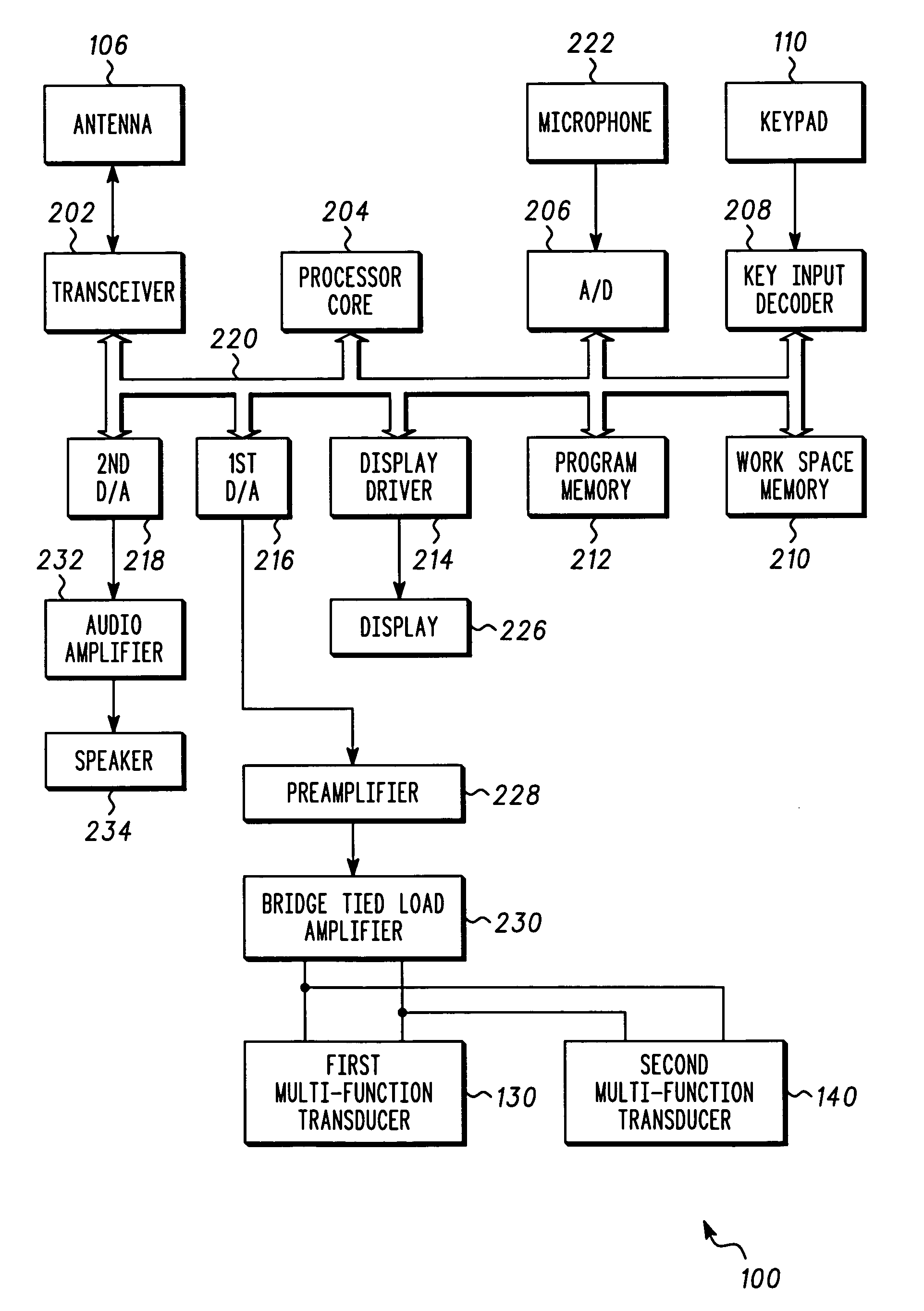
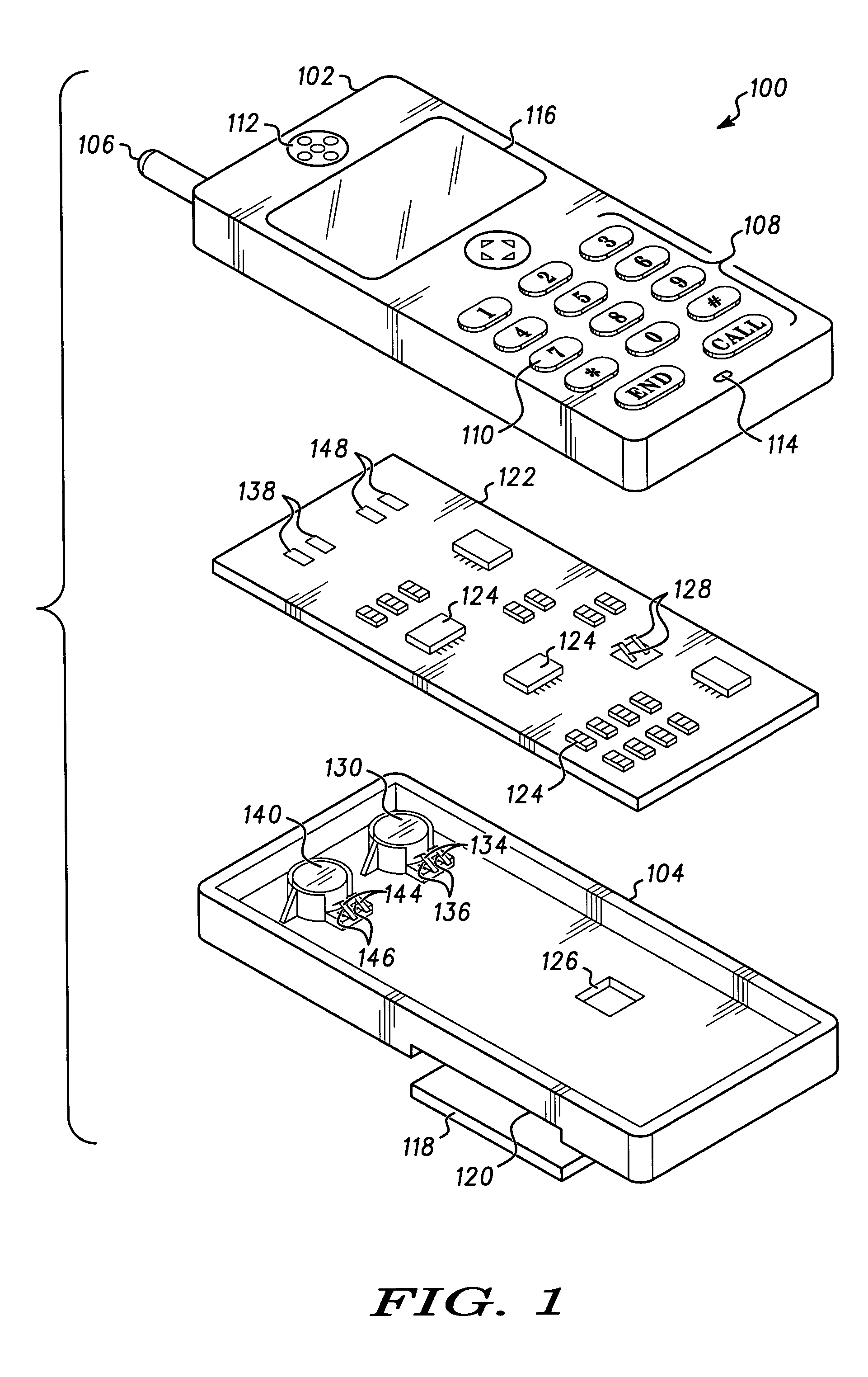
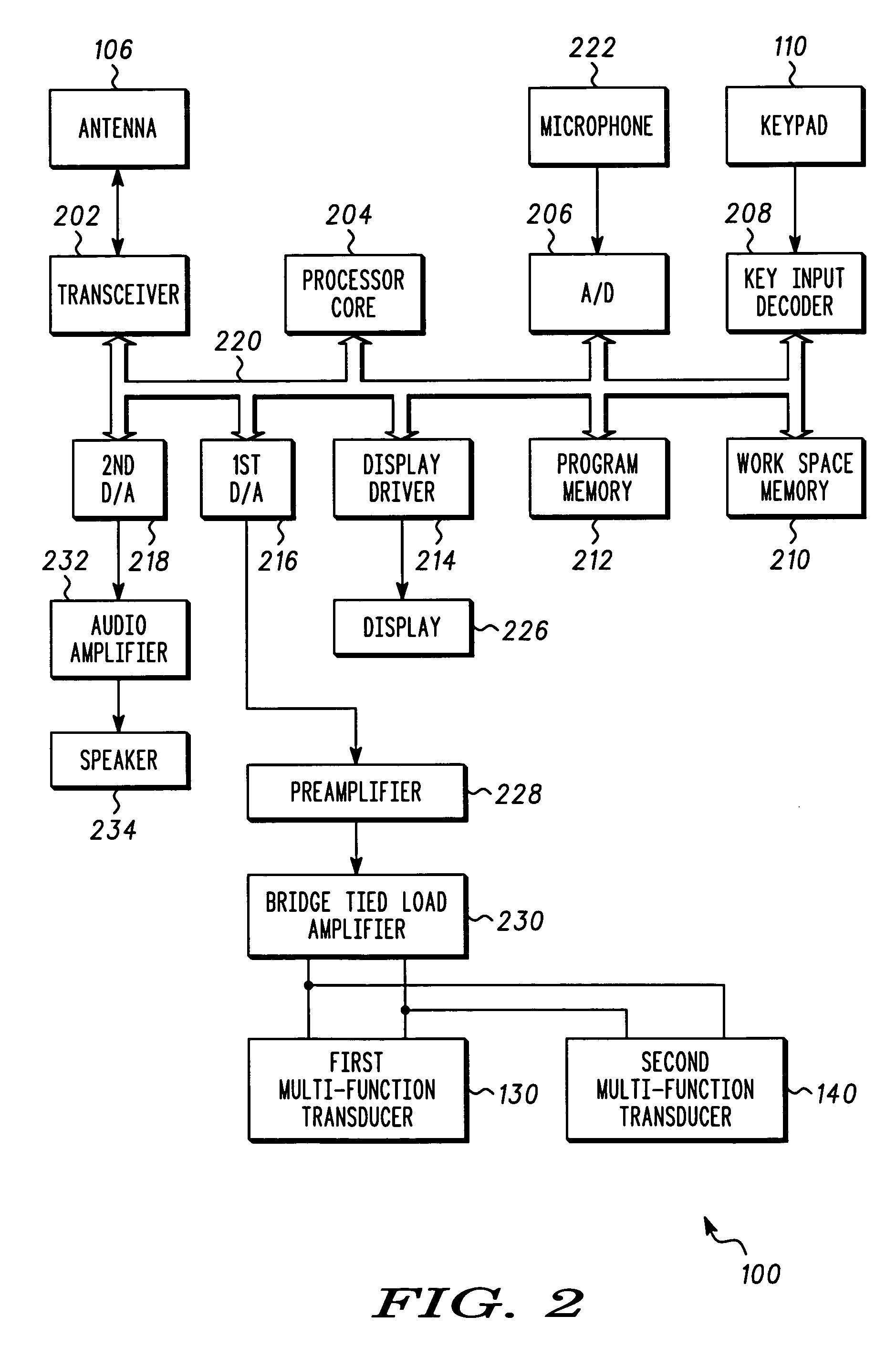
A portable electronic device (100) includes a vibrating transducer having a resilient support and a first mass supported by the first resilient support forming a mechanical resonator, and an electrical circuit coupled to the first vibrating transducer to apply a drive signal. A plurality of tactile vibration transducers (130, 140) can work in unison to produce strong tactile stimulus (216, 228, 230).

Description

FIELD OF THE INVENTION[0001]The present invention relates in general to tactile transducers and methods of driving the same. More particularly, the present invention relates to tactile transducers for use in handheld devices.BACKGROUND OF THE INVENTION[0002]Cellular phones are a ubiquitous sight in today's societies. Presently there is an interest in enhancing the functionality and user experience in using portable electronic apparatus such as cellular telephones. To that end various steps toward making portable electronic devices multimedia capable, such as the introduction of color screens, adding electronic cameras, and enhancing wireless network bandwidth, have been undertaken.[0003]One area in which efforts have been made to improve the user's experience, is audio quality and tactile stimulation. Tactile stimulation is related to audio in the sense that low frequency tactile stimulation can be used as a surrogate for low frequency audio, which would be difficult to generate usi...

Claims


Application Information

Patent Timeline
Patent Type & Authority Patents(United States)
IPC IPC(8): H04B3/36B06B1/02H04BH04M1/03
CPCB06B1/0276B06B2201/20B06B2201/70H04M1/03
Inventor CRANFILL, DAVID B.GUZMAN, SANDRA J.ISABELLE, SCOTT K.SALIBA, RINDALA
Owner GOOGLE TECH HLDG LLC
Learn More