
Threaded push broom locking clip

a technology of locking clip and broom, which is applied in the field ofthreaded push broom locking clip, can solve the problems of cumbersome, awkward and difficult situation, shipping brooms in this fashion, and achieve the effect of effective and efficient secure a push, efficient and efficient transportation, and convenient us

Inactive Publication Date: 2006-11-07
QUICKIE MFG
View PDF10 Cites 49 Cited by
  • Summary
  • Abstract
  • Description
  • Claims
  • Application Information

AI Technical Summary

Benefits of technology

[0006]It is a general object of the present invention to provide an efficient, effective, and economical means of securing the handle of a push broom to its broom head during the transport and merchandising of the push broom.
[0007]It is another object of the present invention to provide a push broom locking clip which will effectively and efficiently secure a push broom handle to the broom head, without risk of separation during transport and merchandising of the push broom.
[0009]It is still a further object of the invention to provide an efficient, effective, and economic means of securing the push broom handle to the cleaning head in order to save valuable cargo and container space, to ensure distribution and sale efficiency, to prevent loss of broom components during transport and merchandising, and to save resources needed to produce and dispose of non-reusable handle to head connectors.

Problems solved by technology

However, while this handle and cleaning head configuration provides a functional push broom, shipping, transport, and merchandising of these brooms presents a problem.
Distribution of push brooms, when forwarded from the manufacturer to wholesalers, retailers, and vendors already connected in the cleaning use mode, i.e., with the handle secured to the threaded hole in the head, results in a cumbersome, awkward and difficult situation.
Shipping brooms in this fashion also takes up valuable cargo and container space.
Displaying assembled push brooms for retail merchandising and sale presents the same handling and spatial problems.
While this has, to a large extent, solved the handling and spatial problems, actually attaching the handles and heads so that they remain secured during transport and shipment and then during the merchandising and display process continues to be a problem.
This causes inconvenience and inefficiency during transport, results in debris and waste from separated broom components and wrappers, leads to actual loss of components, and presents unattractive merchandising displays—all resulting in a general and substantial loss of sales.
However, none of the prior broom handle to head attaching means which are designed exclusively and solely for attaching broom heads to handles for transport and merchandising purposes provides a system to guarantee an effective, practical, and economical system, which allows for the transport and merchandising of a push broom without handle to head separation.

Method used


Image

  • Threaded push broom locking clip
  • Threaded push broom locking clip
  • Threaded push broom locking clip

Examples


Embodiment Construction

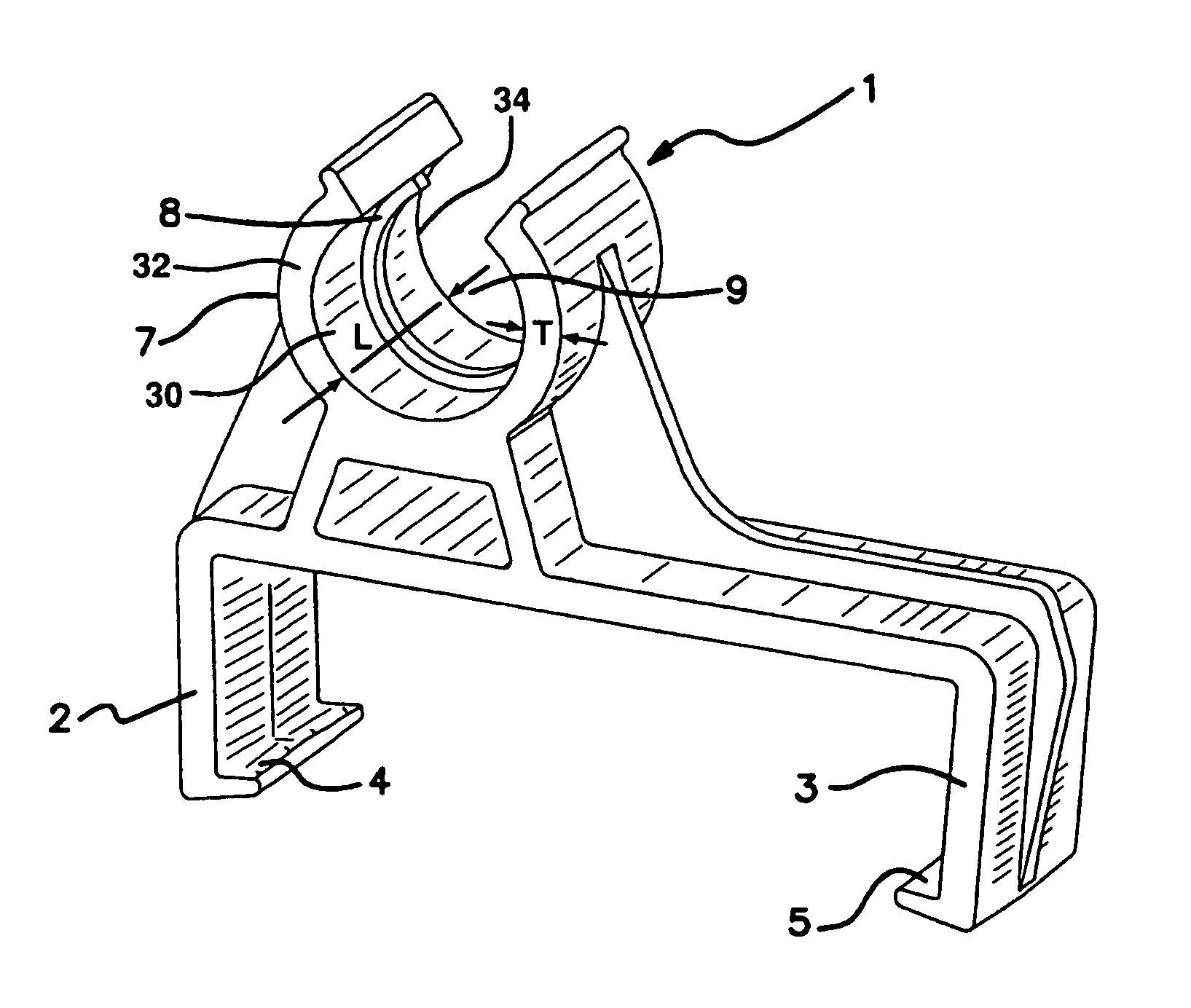
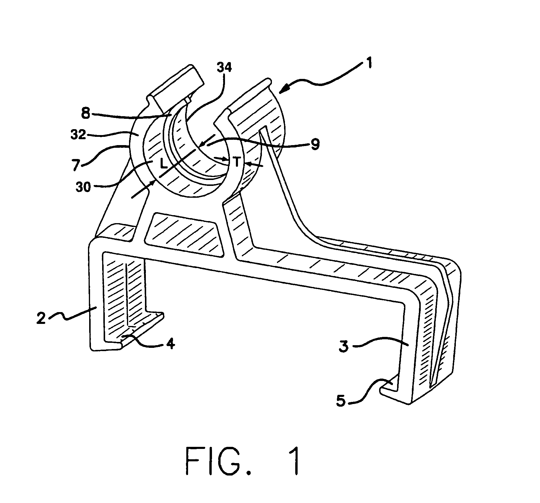
[0020]Push broom locking broom clip 1, shown in FIG. 1, is a unitary body comprising downwardly extending side arms 2 and 3 with inwardly extending lips 4 and S respectively. The upper section of clip 1 comprises partially open cradle 7 with thread 8 and opening 9. Thread 8 extends radially inward from and alone interior surface 30 of cradle 7. The dimensional length L of interior surface 30 extends from curvilinear front surface 32 of cradle 7 to rear surface 34 of the cradle. As best seen in FIG. 1, the dimensional length L of interior surface 30 is greater than the dimensional thickness T of front surface 32. Clip 1 is an integral unit made of resiliently flexible material, such as molded plastic.

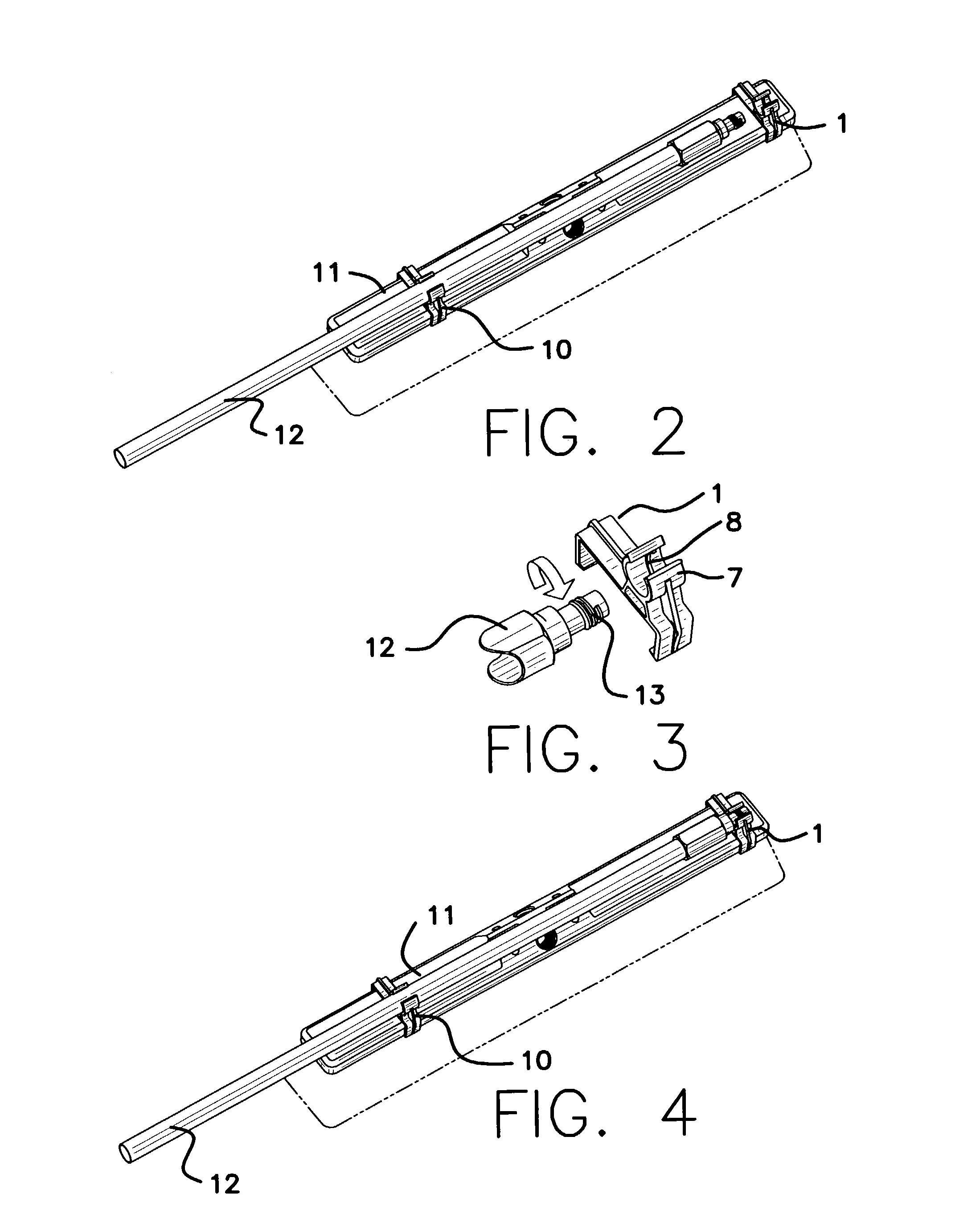
[0021]In use, clip 1 is mounted on broom head 11 by placing the clip over the top of the support member of the head and slightly extending side arms 2 and 3 outward. As side arms 2 and 3 close over and around the top of head 11, lips 4 and 5 secure the clip onto the head, as seen in FIG....


PUM


Abstract

An integrally formed locking clip has a unitary body and downwardly extending lateral side arms. The clip is made of resiliently flexible material which allows the side arms to extend over and around the top support member of a push broom head and attach to the broom head. The clip has an upper section consisting of a threaded opening which is configured to accept and threadably engage the threaded end connection of the handle of the push broom. When so engaged, the handle is securely mounted on and along the longitudinal axis of the broom head. The upper section of the clip may be formed of a closed circular threaded ring or a partially opened threaded cradle.

Description

BACKGROUND OF THE INVENTION[0001]Push brooms have long been used as an effective cleaning tool. The standard push broom consists of a separable elongated handle and a brush or cleaning head. Usually the brush head is made up of bristles and a rigid bristle supporting base, often made of wood, plastic, light metal, or other hard material. The base routinely has two centrally located holes in its upper surface for receiving the handle. One hole is located on one side of the head and the second hole is located on the other side of the head. This allows the handle to be switched from one hole to the other, when the bristles become worn in one pushing direction. The holes are threaded to allow engagement with the end of the handle which has corresponding threads. The handle is easily screwed into the base in the cleaning use mode of the broom.[0002]However, while this handle and cleaning head configuration provides a functional push broom, shipping, transport, and merchandising of these ...

Claims


Application Information

Patent Timeline
Patent Type & Authority Patents(United States)
IPC IPC(8): A44B21/00A44B99/00A46B17/02B25G3/36E04G7/00F16B1/00
CPCA46B17/02Y10T24/44769Y10T403/7129A46B2200/302
Inventor WEAVER, JACE A.
Owner QUICKIE MFG
Learn More