Light bulb catcher for use with a changing device

a technology for catching devices and light bulbs, which is applied in the direction of wrenches, screwdrivers, kitchen equipment, etc., can solve the problems of bulb falling, bulb falling, and injury to the bulb changer as well as any other individual in the immediate area, and achieve the effect of facilitating the manipulation of light bulbs

Inactive Publication Date: 2006-11-07
SAUNDERS LAMOINE
View PDF9 Cites 42 Cited by
  • Summary
  • Abstract
  • Description
  • Claims
  • Application Information

AI Technical Summary

Benefits of technology

[0008]The present invention may be readily adapted to a variety of light bulb changing devices and methods and systems for light bulb changing. Embodiments of the present invention may provide, among other benefits: a biased, slidably connected or deformable catcher that surrounds the sides of a light bulb attachment mechanism and also allows easier manipulation of the light bulb than the prior light bulb catches. The present invention also may provide a rotatably connected catcher which allows a pole connected to the attachment mechanism and the attachment mechanism to rotate with the catcher remaining stationary in order to prevent the catcher from damaging the ceiling or getting caught on another structure when the light bulb is being removed or installed. An embodiment of the present invention may also provide a telescoping pole that is biased in order to allow the user to apply pressure to the light bulb without breaking it.

Problems solved by technology

The problem with most prior devices has been the danger of the light bulb disengaging from the attachment mechanisms resulting in the light bulb falling.
Due to the height of the light bulb, when it falls and shatters the glass shards may cause injury to the bulb changer as well as any other individual in the immediate area.
The unsteady pole movement often results in the bulb striking against the socket, ceiling, fixture or a recessed wall and dislodging the light bulb or breaking the vacuum seal, resulting in the bulb falling.
Additionally, dust and grime build-up on the surface of a light bulb creates an imperfect suction coupling, leading to a premature detachment of the light bulb while it is being held by the suction attachment.
Furthermore, when lowering the light bulb it is generally necessary to tilt the pole, causing a loosely attached light bulb to fall.
The falling light bulb creates a hazardous and dangerous projectile.
In addition, trying to replace a burned out light bulb can become a costly venture as new light bulbs fall and break during the installation process.
The umbrella 13 is rigid and cumbersome, creating many problems of its own.
Light bulbs 16 in hard to reach places can be even harder to reach due to the fact that the umbrella 13 is so wide that it will not fit into small enclosed areas which might contain a light bulb 16.
The umbrella 13 can also cause problems when the user 11 attempts to rotate the pole 12 in order to loosen the light bulb 16.
Also, if the light bulb does fall and is caught by the Tse umbrella structure, the user must still try to lower the pole without having the bulb fall out of the catch.

Method used


Image

  • Light bulb catcher for use with a changing device
  • Light bulb catcher for use with a changing device
  • Light bulb catcher for use with a changing device

Examples


Embodiment Construction

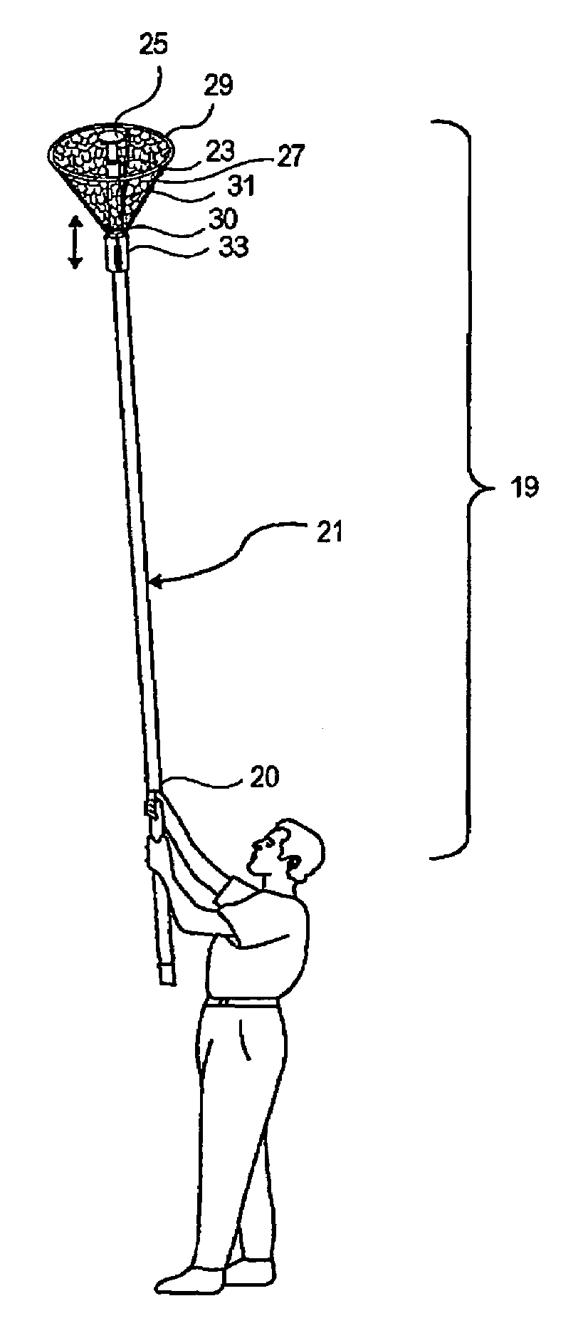
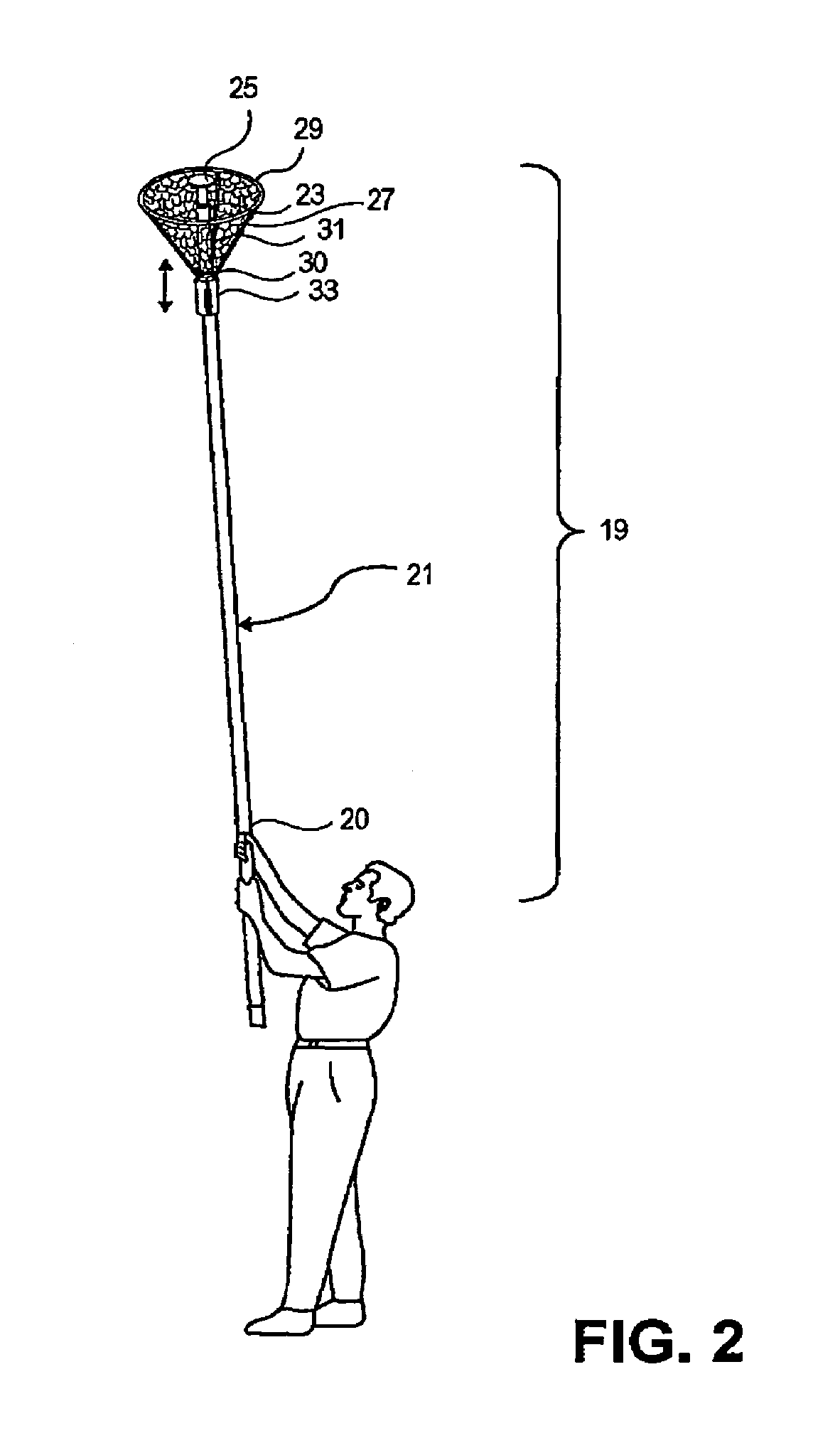
[0018]As discussed above, embodiments of the present invention relate to a catch. Generally, a catch configured to catch a falling light bulb according to an embodiment of the present invention may include a pole, a proximal end of a catcher connected to a work product end of the pole, and an attachment mechanism connected to the work product end of the pole. The sides of the attachment mechanism may be surrounded by the catcher.

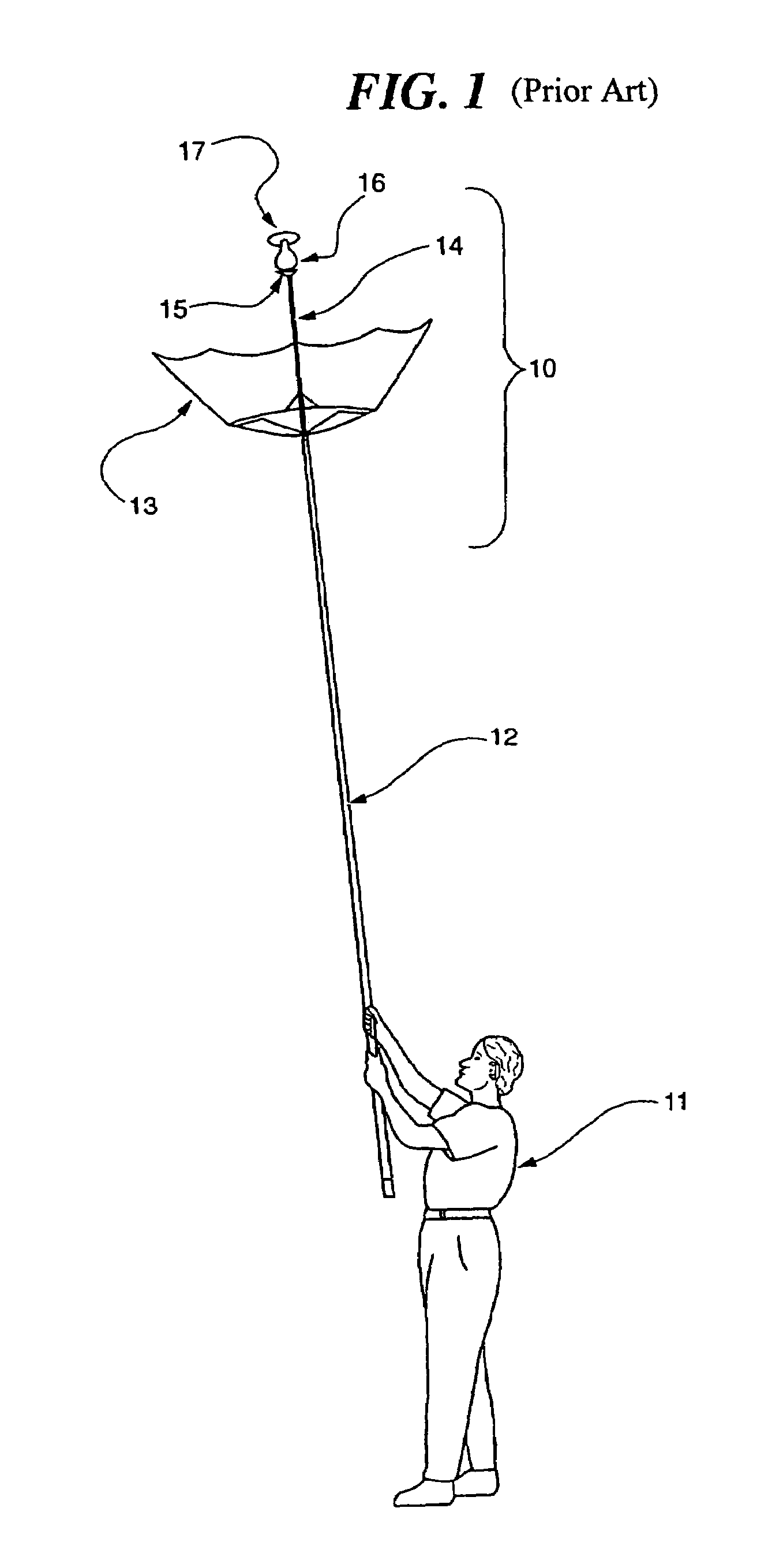
[0019]FIG. 1 shows a prior art light bulb changer wherein a user 11 uses a pole 12 which has a bulb securing attachment 15 attached to distal pole end 14. Attachment 15 engages a bulb 16 in a socket 17. Placed around the pole 12 is an umbrella like catch 13. The catch 13 is opened prior to lifting the pole 12 into position. It should be appreciated that as the pole 12 is raised or lowered into position, should the bulb 16 disengage from the attachment 15, it could easily either miss the catch completely or roll out of the catch. Even if the bulb lands in the...


PUM


Abstract

A light bulb catch is disclosed that comprises a catcher and an attachment mechanism. The catcher may be rotatably or slideably connected to a pole through a rotatable connection and connector. A distal end of the catcher may also be biased away from a proximal end of the catcher or the catcher may be deformable, in order to increase maneuverability and allow the catcher to be moveable between an extended and retracted position. A work product end of the pole, which is contained in the catcher and connects to the attachment mechanism, may telescope and may also be biased towards a forward position, moveable to a rearward position, allowing the user to apply pressure to the light bulb changing device without damaging the bulb. The catch may have many purposes besides simply changing light bulbs as will be realized by those in the art.

Description

BACKGROUND OF THE INVENTION[0001]1. Technical Field[0002]This invention relates to a light bulb catching device for use in changing light bulbs in elevated or hard to reach locations such as high ceilings where direct handling of the light bulbs cannot readily be done by the light bulb changer.[0003]2. Background Art[0004]There are many extension devices for use in changing light bulbs that are hard to reach. Most of these devices focus on methods of removing a light bulb from a light socket that is elevated, specifically on attachment mechanisms that allow the user to unscrew the light bulb from a distance. These include mechanisms such as suction cups or capture attachments.[0005]The problem with most prior devices has been the danger of the light bulb disengaging from the attachment mechanisms resulting in the light bulb falling. Due to the height of the light bulb, when it falls and shatters the glass shards may cause injury to the bulb changer as well as any other individual in...

Claims


Application Information

Patent Timeline
Patent Type & Authority Patents(United States)
IPC IPC(8): H01K3/32
CPCH01J9/003H01K3/32
Inventor SAUNDERS, LAMOINE
Owner SAUNDERS LAMOINE
Why Eureka
Try Eureka