
Bead lock

a technology of beads and beads, applied in the field of beads, to achieve the effect of facilitating communication

Active Publication Date: 2006-11-07
SMITH ROGER
View PDF16 Cites 11 Cited by
  • Summary
  • Abstract
  • Description
  • Claims
  • Application Information

AI Technical Summary

Benefits of technology

The system effectively maintains tire bead engagement with the rim at low pressures, enhances traction, and reduces the risk of rim damage while being more durable and affordable than existing solutions.

Problems solved by technology

However, provided the material is sufficiently flexible and incompressible, the bead spacer may be made from non-woven materials which include plastic polymeric materials, rubber compounds, metal and silicon-based compounds or a mixture or composite thereof.

Method used


Image

  • Bead lock
  • Bead lock
  • Bead lock

Examples


first embodiment

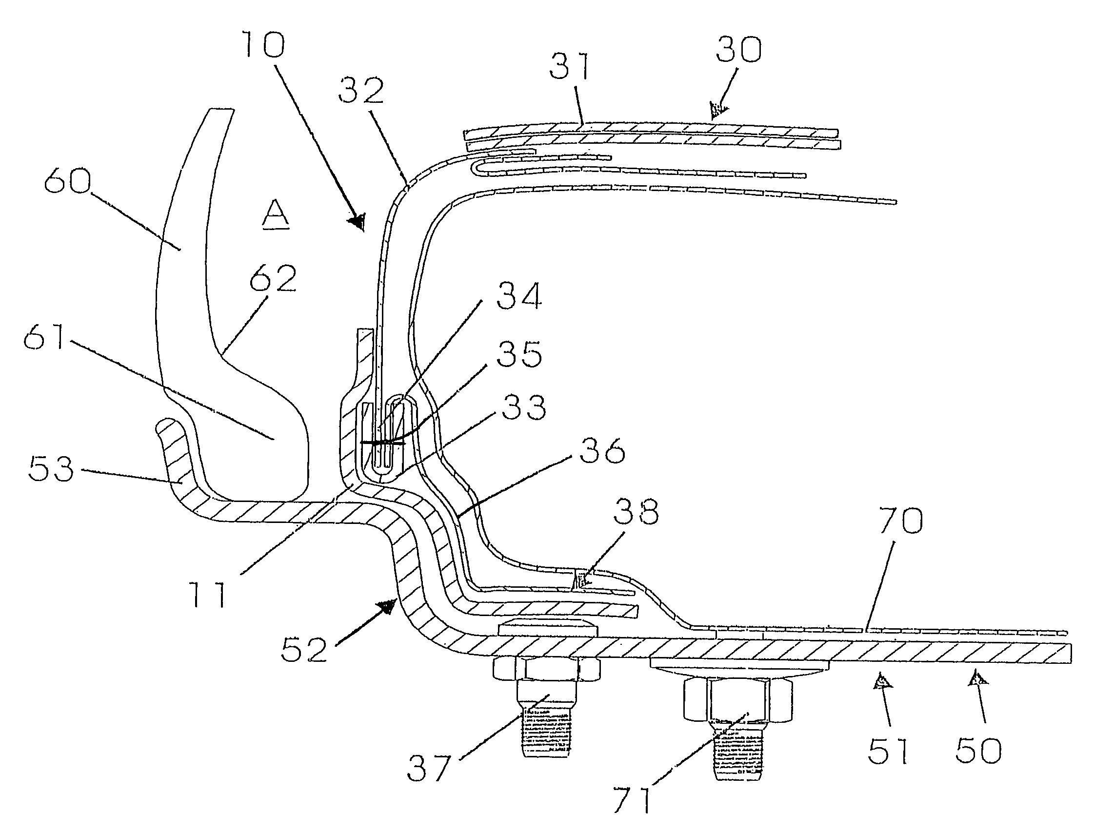
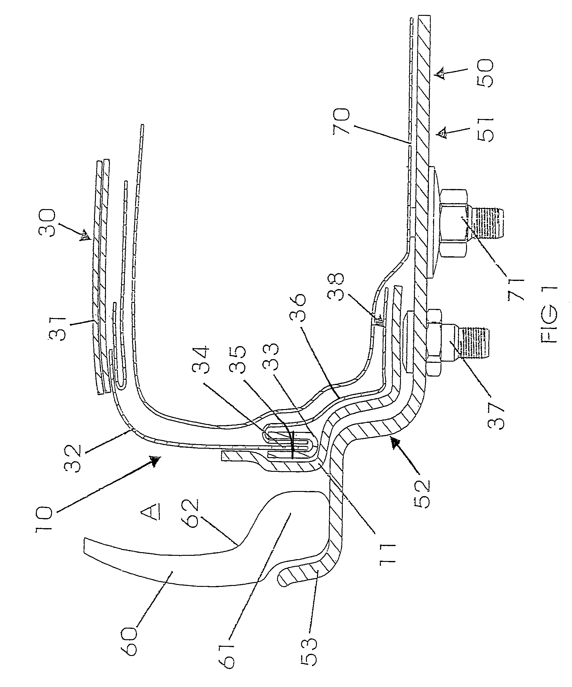
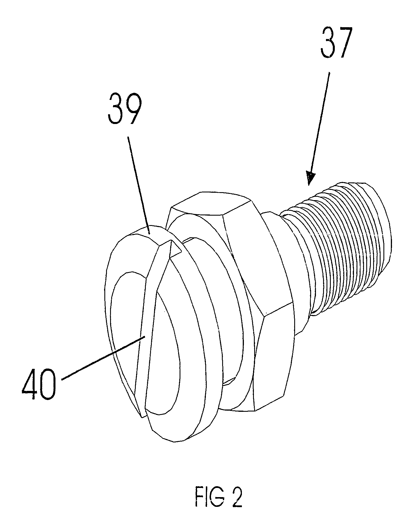
[0033]Also stitched within the folds of the insert bead 33 in the first embodiment is an apron 36 in use depending from the insert bead 33 down to the area surrounding an insert valve 37.

[0034]Also attached by stitching to the insert bead 33 are elongate spacers 11 extending from above the insert bead 33 down to the valve area 38 surrounding the insert valve 37. As best seen in FIG. 7, the insert bead 33, the elongate spacers 11 and the apron 36 are secured together whereby to provide a permanent and enduring attachment to one another, whether by stitching, welding, heat fusion, vulcanisation, adhesive or other suitable means.

[0035]In use, the internal tire space marked A of the pneumatic tire 60 is inflated by attaching inflating means to the insert valve 37 and forcing air through the valve 37 into a passage or passages 12 defined by the elongate spacers 11, the most effective passage being the central passage 12a corresponding to a corridor defined by each adjacent pair of elonga...

fourth embodiment

[0045]In the fourth embodiment shown in FIG. 6, the bead spacer may comprise a single elongate spacer 28 of sufficient depth or thickness to define narrow passageways 29 either side thereof. Advantageously, the single elongate spacer 28, where made from sufficiently flexible and foldable material, can be folded over in manufacture to increase its spacing effect.

[0046]Although many materials will be suitable for the insert casing, the desirability for lightweight, non-extensible materials makes woven, synthetic or natural fibres most advantageous. In a particularly preferred embodiment, the side wall 32 and inner lining adapted to bear against the inner tube 70 is made from 100% polyester woven fabric (500 DR×500 DR). The wide band 31 limiting radial expansion of the inner tube 70 may be made from 100% polyester narrow woven fabric. The insert bead 33 may be made from 100% polyester narrow woven fabric. The elongate spacers 11, 22, 25, 2833 may also be made from 100% polyester narrow...


PUM


Abstract

A bead lock including an insert casing and a bead spacer for providing an air passageway in a vehicle tire to be mounted on a wheel rim on which is located an insert valve and a rim lip for retention of the vehicle tire bead, the insert casing including an insert bead adapted to push against the tire bead and to hold the tire bead firmly against the inner surface of the rim lip, the inner wall of the vehicle tire and the outer surface of the insert casing defining an internal tire space to be pressurized for inflation of the vehicle tire or depressurized for the deflation of the vehicle tire via the insert valve, the tire bead and the insert bead interposed between the internal tire space and the insert valve, the bead spacer extending from the insert bead to an insert valve area corresponding in use to the insert valve location whereby to define at least one air passage for communication of the internal tire space with the insert valve, wherein the bead spacer is made of material sufficiently flexible to substantially conform to the contours of the wheel rim and sufficiently incompressible to provide the air passageway.

Description

FIELD OF THE INVENTION [0001]The present invention relates to a bead lock for off-road or low tire pressure applications.BACKGROUND OF THE INVENTION [0002]The following description of the prior art is not intended to be, nor should it be interpreted as, an indication of the common general knowledge pertaining to the invention.[0003]A common problem faced in off-road applications is that the tire bead may become separated from the wheel rim when operating the vehicle at low tire pressures. Particularly in off-road applications, the tires are commonly subjected to substantial lateral forces and, without reinforcement, a standard tire bead may become disassociated from the wheel rim. This is particularly so in off-road racing, extreme off-road conditions or where very low tire pressures are involved.[0004]Another issue involves use of low profile tires. In such tires the space between road hazards such as small solid objects and the wheel rim is small and may lead to rim damage where t...

Claims


Application Information

Patent Timeline
Patent Type & Authority Patents(United States)
IPC IPC(8): B60C17/01B60C5/22B60C7/24B60C15/028B60C15/032
CPCB60C5/22B60C17/01B60C15/032Y10T152/10594
Inventor SMITH, ROGER
Owner SMITH ROGER
Learn More