Foreign matter removing device

a foreign matter and removal device technology, applied in vehicle cleaning, vehicle components, multiple wheel assembly, etc., can solve the problems of above-described prior arts, become evident, etc., and achieve the effect of removing foreign objects favorably, removing foreign objects reliably, and hardly damaging tires or interferes

Inactive Publication Date: 2006-11-07
KOMATSU LTD
View PDF13 Cites 23 Cited by
  • Summary
  • Abstract
  • Description
  • Claims
  • Application Information

AI Technical Summary

Benefits of technology

[0012]The present invention is made in view of the above-described problem, and has its object to provide a foreign matter removing device which hardly damages a tire or interferes with traveling, and is capable of removing foreign matters reliably.
[0014]In the foreign matter removing device, the foreign matter removing member is suspended from an upper position into the space of at least the one double tire, and the foreign matter removing member may have such a length that a height of the tip end portion is lower than a height of a center of the hub when a distance in a vertical direction from a mounting position of a base end portion of the foreign matter removing member to the hub becomes maximum. According to this, the tip end portion is lower than the height of the center of the hub in any case, and therefore the tip end portion does not ride over the hub, thus making it possible to remove the foreign matter favorably.

Problems solved by technology

However, the above-described prior arts have the problems as described below.
However, even the foreign matter removing device using the stone removing rod 17 as above has the following problems.
However, the spacer 19 is not required as a result that the double tire 12 is made a flange type, and therefore such a problem becomes evident.

Method used


Image

  • Foreign matter removing device
  • Foreign matter removing device
  • Foreign matter removing device

Examples


Embodiment Construction

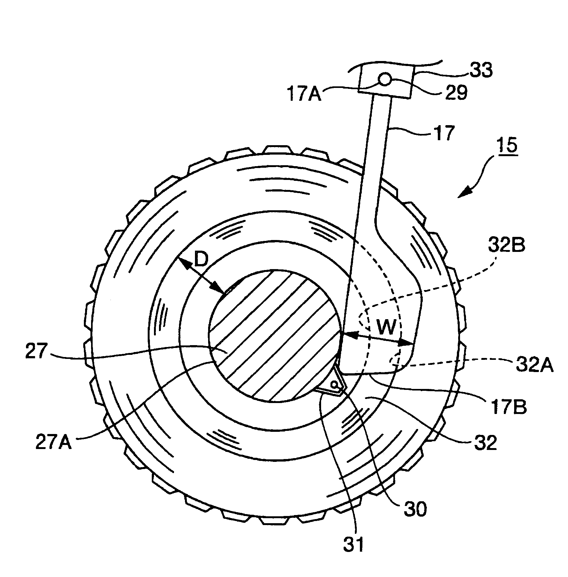
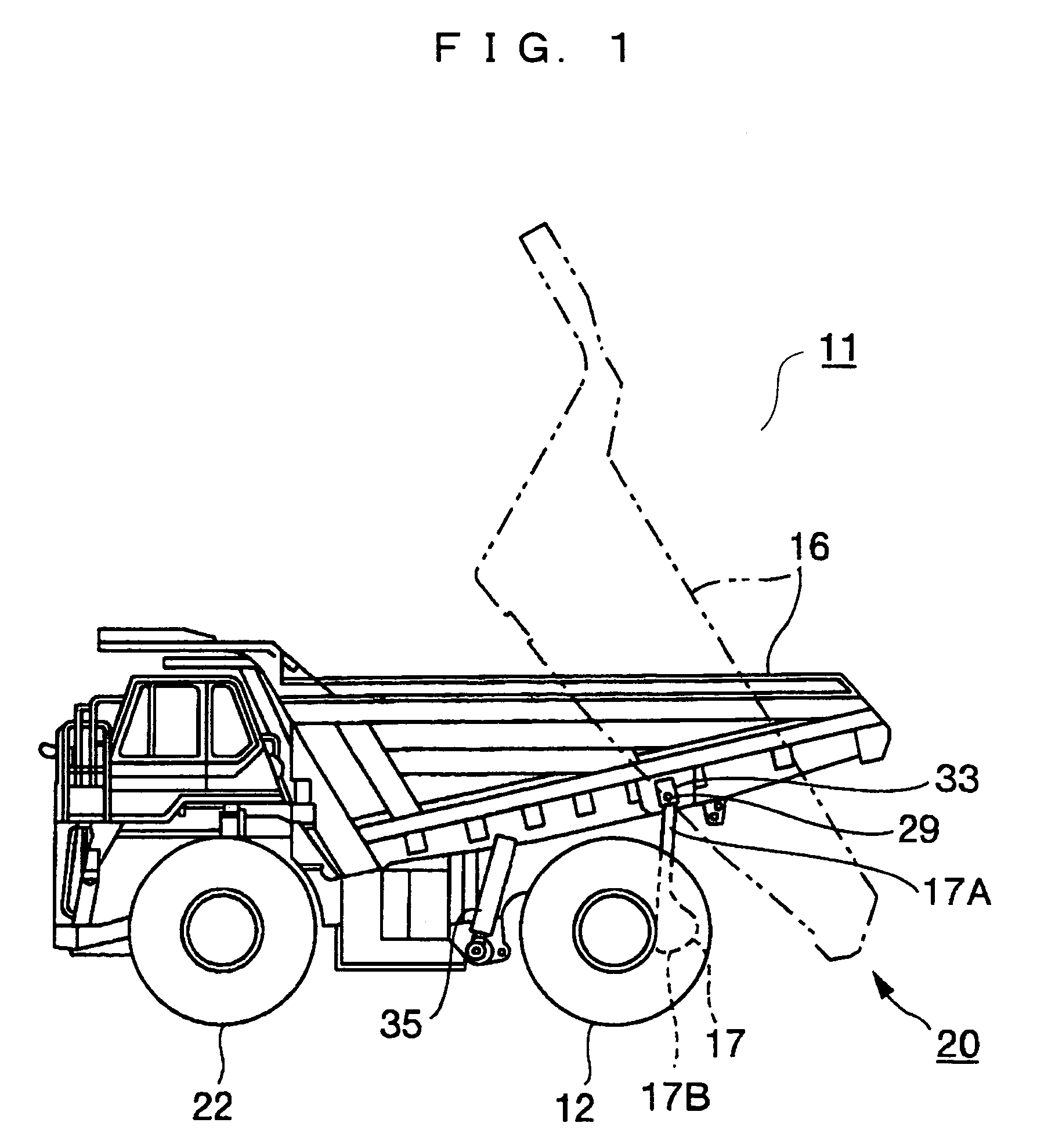
[0032]A preferred embodiment according to the present invention will be explained in detail with reference to the drawings, hereinafter. In FIG. 1, a dump truck 11 includes a vehicle body 20 including front and rear wheels, and a body 16 loaded on an upper part of the vehicle body 20. The body 16 is capable of being raised and lowered by extension and contraction of a body cylinder 35. The front wheels are steering wheels 22 which perform a steering operation, and the rear wheels are double tires 12. In a space of the double tire 12, a stone removing rod 17 according the embodiment is inserted as in FIG. 14.

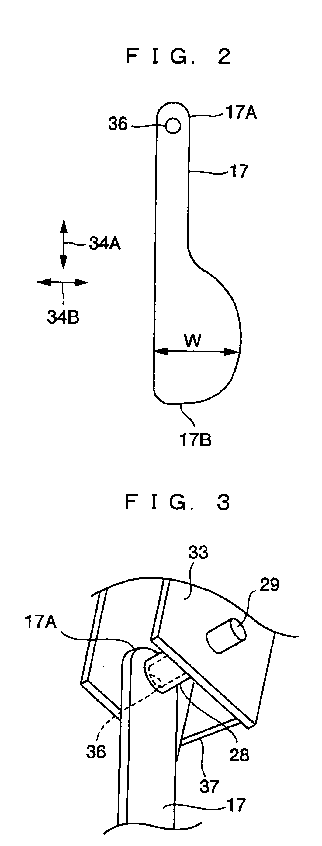
[0033]In FIG. 2, an upper end portion of the stone removing rod 17 is provided with a pin hole 36 into which a fixing pin 29 is inserted. An up-and-down direction in FIG. 2 is called a longitudinal direction (the arrow 34A) of the stone removing rod 17, and a direction perpendicular to the longitudinal direction and approximately corresponding to a traveling direction of the vehi...


PUM


Abstract

A foreign matter removing device which is capable of reliably removing foreign matter from between a double tire includes at least one foreign matter removing member interposed in a space of at least one double tire. A dimension in a width direction of the foreign matter removing member in a vicinity of a tip end portion thereof is larger than a dimension in a diameter direction from an outer peripheral portion of a hub, on which the double tire is fitted, to an outer peripheral portion of a rim of at least the one double tire.

Description

TECHNICAL FIELD[0001]The present invention related to a foreign matter removing device for removing foreign matters caught in a space of a double tire.BACKGROUND ART[0002]A foreign matter removing device for removing foreign matters such as stones, which are caught in a space of a double tire, is conventionally known (for example, see Japanese Patent Application Laid-open No. 11-43022). FIG. 11 and FIG. 12 show an essential part of a vehicle to which a foreign matter removing device disclosed in Japanese Patent Application Laid-open No. 11-43022 is mounted. As shown in FIG. 11, a double tire 12 is what is formed by arranging two tires (hereinafter, called an outer tire 15 and an inner tire 14) at an end portion of a shaft 21 in parallel via a spacer 19 or the like so as to have a predetermined gap. In a working vehicle 11 having the double tire 12, foreign matters such as gravel are sometimes caught between the outer tire 15 and the inner tire 14. Such foreign matters sometimes dama...

Claims


Application Information

Patent Timeline
Patent Type & Authority Patents(United States)
IPC IPC(8): B60S1/68B60B11/00
CPCB60B11/00
Inventor KINOSHITA, YOICHI
Owner KOMATSU LTD
Why Eureka
Try Eureka