Insertion device for intraocular lens

a technology of insertion device and intraocular lens, which is applied in the field of intraocular lens insertion device, can solve the problems of inability to form the tip end of the push rod to have a large diameter, the tip end of the insertion tube may be broken, etc., and achieves the effect of reducing the deformation of the push rod from the center axis, reducing the deformation of the push rod, and reducing the siz

Active Publication Date: 2006-11-07
STAAR JAPAN
View PDF11 Cites 79 Cited by
  • Summary
  • Abstract
  • Description
  • Claims
  • Application Information

AI Technical Summary

Benefits of technology

[0017]An object of the present invention is to provide an intraocular-lens insertion device which can reduce deflection of a push rod at a lens placement section of the insertion device, which deflection would otherwise arise at the time of inserting an intraocular lens as a result of a large space of the lens placement section, to thereby solve the problem involved in the conventional device.
[0018]Another object of the present invention is to provide an intraocular-lens insertion device which can push an intraocular lens within the lens placement section by use of a larger push portion, to thereby reduce the load acting on the intraocular lens.
[0019]In order to achieve the above objects, the present invention provides an insertion device for deforming a deformable intraocular lens to a reduced size and inserting the deformed lens into an eye through an insertion tube. The insertion device comprises a push rod disposed for pushing and inserting the lens into the eye, and a posture control member disengagably engaged with a tip end portion of the push rod. The posture control member prevents deflection of the push rod from a center axis. The engagement between the posture control member and the push rod is broken when the push rod arrives at a predetermined position during a step of advancing the push rod.

Problems solved by technology

However, a conventional intraocular-lens insertion device of the former type in which a lens is folded by use of a taper portion of a holding member involves the following problem.
Since a space of the holding member for placement of an intraocular-lens is large, the posture of a push rod within the space cannot be controlled, and consequently the push rod deflects in the course of a step of advancing the push rod.
When the push rod deflects, the intraocular lens may be caught between the inner wall surface of the holding member and the push rod with resultant breakage of the intraocular lens, or a tip end portion of an insertion tube of the insertion device may be broken.
Therefore, in the intraocular-lens insertion device of the type in which a lens is folded by use of the taper portion (i.e., the insertion tube), the tip end of the push rod cannot be formed to have a large diameter, even though the insertion device has a large space at its lens placement section.

Method used


Image

  • Insertion device for intraocular lens
  • Insertion device for intraocular lens
  • Insertion device for intraocular lens

Examples


Embodiment Construction

[0033]An embodiment of the present invention will be described with reference to the drawings.

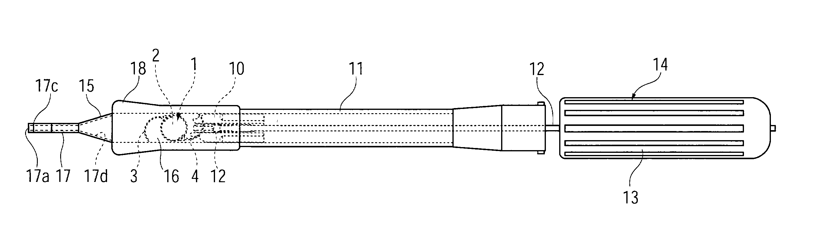
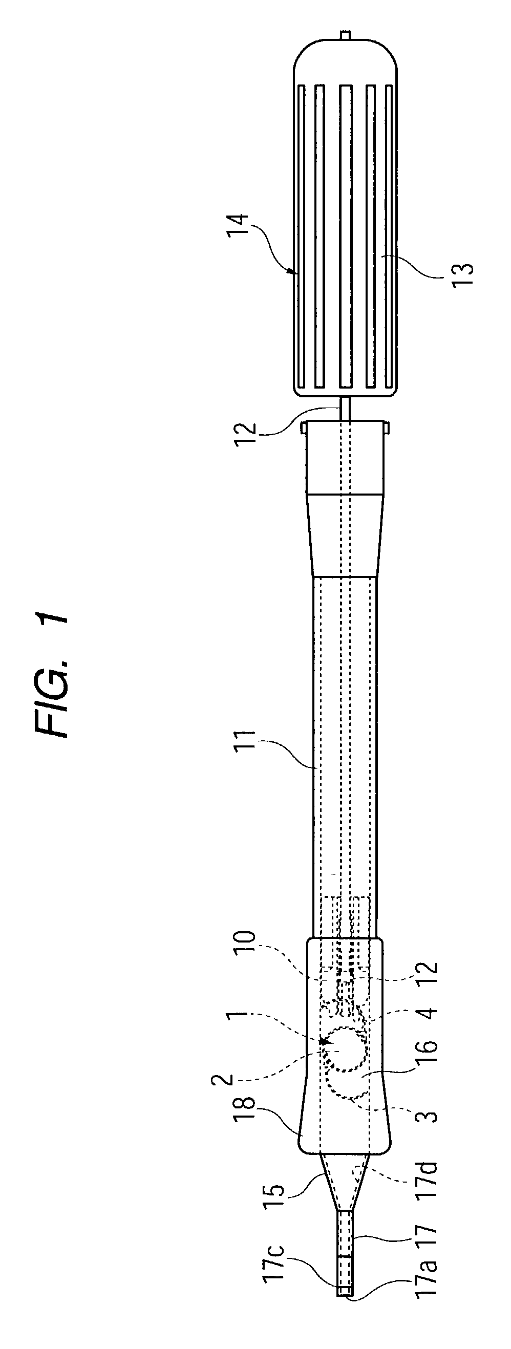
[0034]FIG. 1 is a plan view of an intraocular-lens insertion device according to the present invention.

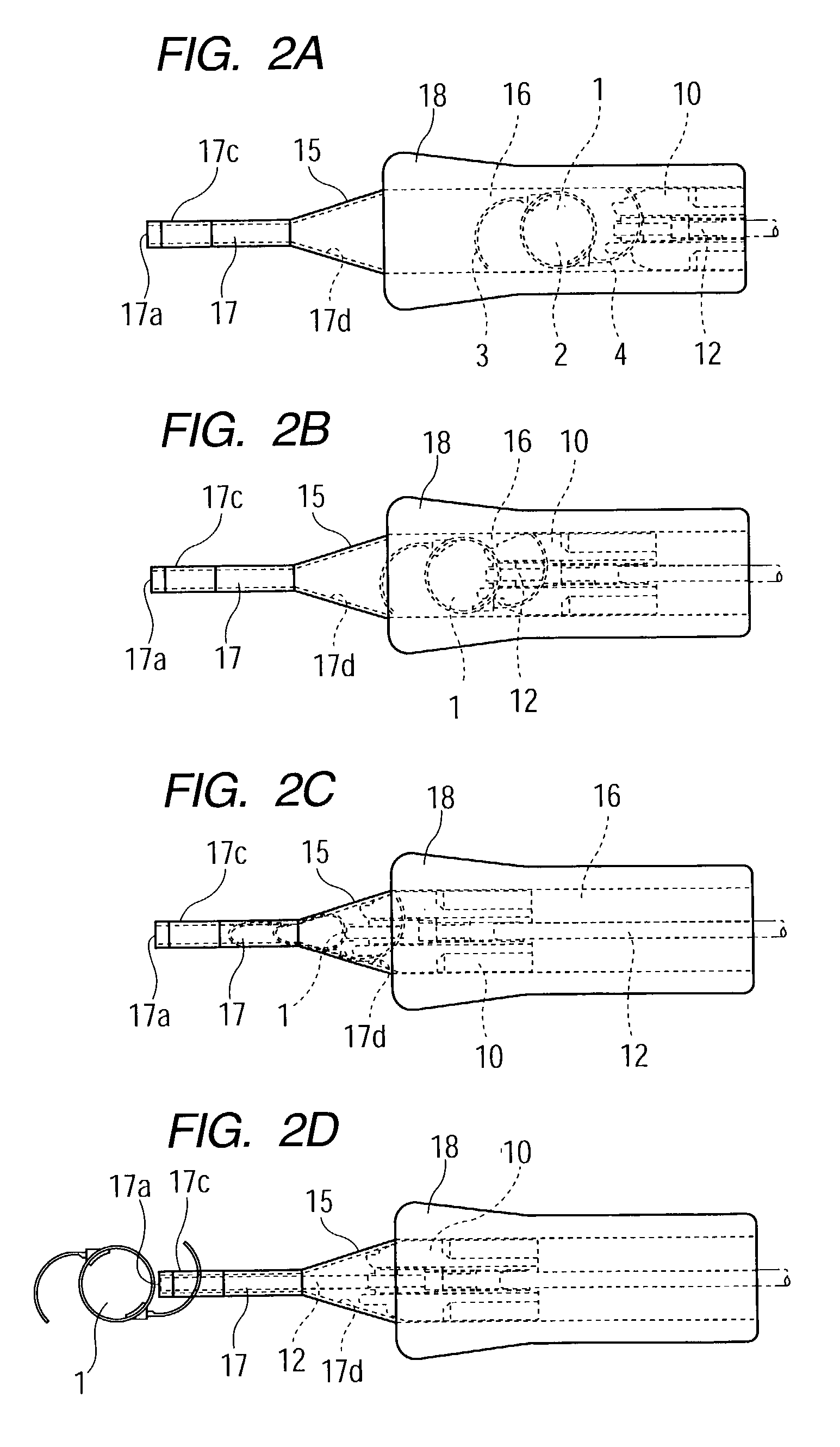
[0035]The insertion device is mainly composed of a generally tubular main body 11, a pusher mechanism 14, and a holding member 18. The pusher mechanism 14 includes a push rod 12 inserted into the main body 11, and a threaded sleeve 13 to be screw-engaged with a rear end of the main body 11. The holding member 18 includes a lens placement section 16, which, instead of having a hinge portion, includes a taper portion 15 for deforming an intraocular lens 1 into a smaller size; and an insertion tube 17, which projects from the tip end of the taper portion 15. The holding member 18 is fixedly attached to the tip end of the main body 11. Specifically, a depressed portion and a projecting portion are formed on the tip end of the main body 11 and the rear end of the holding member 18, respectively...


PUM


Abstract

An insertion device is used to deform a deformable intraocular lens to a reduced size and insert the deformed lens into an eye through an insertion tube. The insertion device includes a push rod for pushing and inserting the lens into the eye, and a posture control member disengagably engaged with a tip end portion of the push rod. The posture control member prevents deflection of the push rod from a center axis. The engagement between the posture control member and the push rod is broken when the push rod arrives at a predetermined position during a step of advancing the push rod.

Description

BACKGROUND OF THE INVENTION[0001]1. Field of the Invention[0002]The present invention relates to a device for inserting a deformable intraocular lens into the eye. Examples of such a deformable intraocular lens include a deformable intraocular lens that is inserted into the eye in place of the natural lens when the latter is physically extracted because of cataracts, and a vision correction lens that is inserted into the eye for the sole purpose of vision correction.[0003]2. Description of the Related Art[0004]In general, during cataract surgery, an intraocular lens is inserted into the eye, from which the natural lens has been removed (lens-removed eye), such that the intraocular lens is located in the original position previously occupied by the natural lens and restores vision. Various studies on the material and shape of such an intraocular lens have been carried out since Ridley performed the first implantation of an artificial lens in 1949.[0005]In recent years, in addition to...

Claims


Application Information

Patent Timeline
Patent Type & Authority Patents(United States)
IPC IPC(8): A61F9/00A61F2/16
CPCA61F2/1664
Inventor KOBAYASHI, KENICHIKIKUCHI, TOSHIKAZU
Owner STAAR JAPAN
Why Eureka
Try Eureka