Varying circumferential spanned connectors in a stent

a technology stents, which is applied in the field of varying circumferential spanned connectors in stents, can solve the problems of affecting the stability of the stent, affecting the stent, and affecting the stent's elasticity,

Inactive Publication Date: 2006-11-07
BOSTON SCI SCIMED INC
View PDF96 Cites 77 Cited by
  • Summary
  • Abstract
  • Description
  • Claims
  • Application Information

AI Technical Summary

Problems solved by technology

Increased flexibility in a stent, however, typically comes at the expense of scaffolding strength.
Moreover, design features which may result in increased flexibility may also result in protruding edges which may damage vessels walls or catheter balloons during delivery of the stent through tortuous vasculature.

Method used


Image

  • Varying circumferential spanned connectors in a stent
  • Varying circumferential spanned connectors in a stent
  • Varying circumferential spanned connectors in a stent

Examples


Embodiment Construction

[0031]While this invention may be embodied in many different forms, there are described in detail herein specific embodiments of the invention. This description is an exemplification of the principles of the invention and is not intended to limit the invention to the particular embodiments illustrated.

[0032]For the purposes of this disclosure, like reference numerals in the figures shall refer to like features unless otherwise indicated.

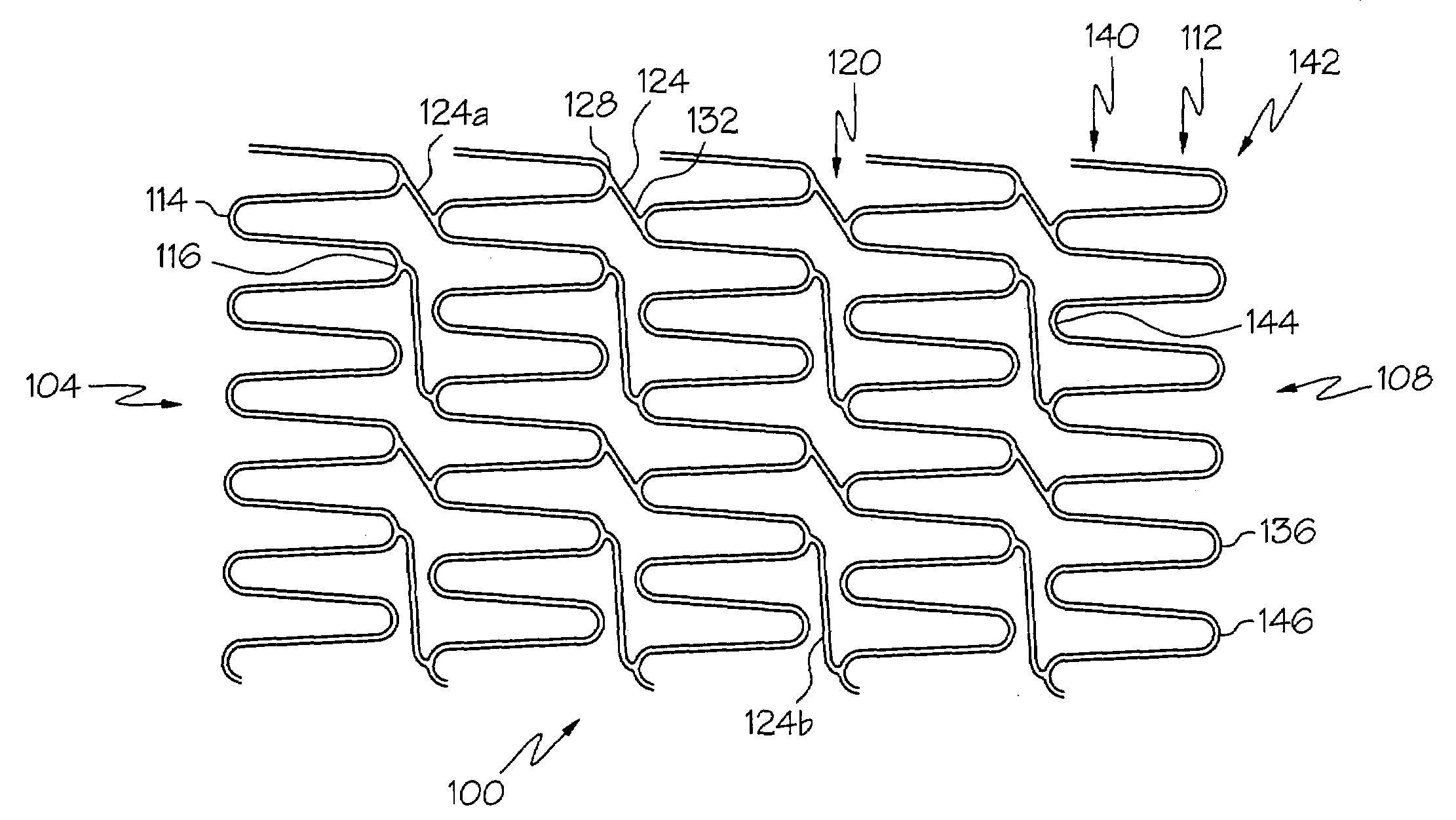
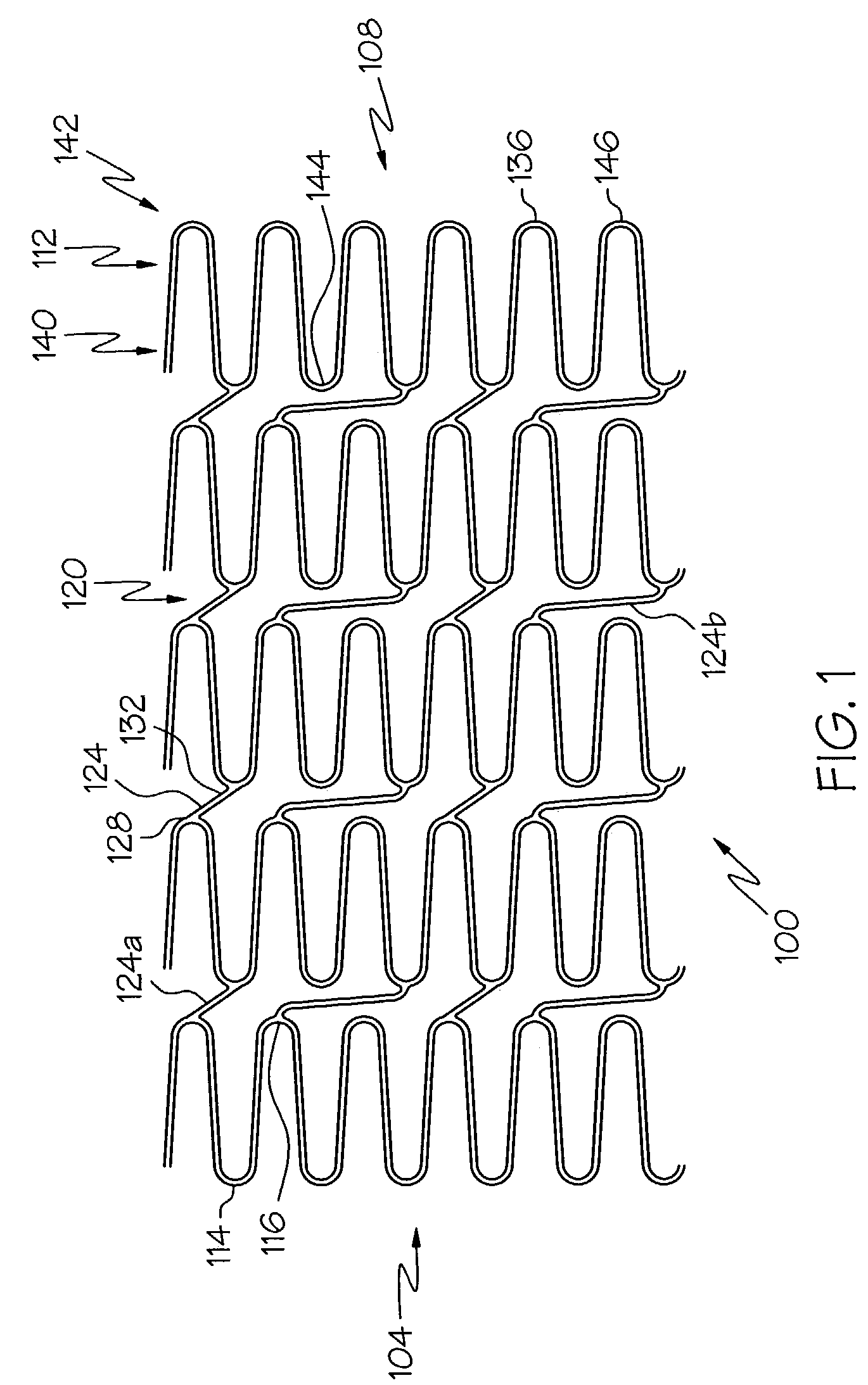
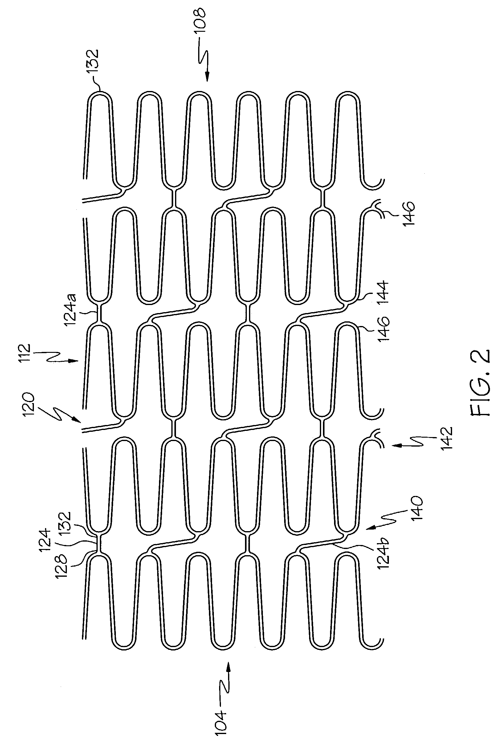
[0033]In one embodiment, the invention is directed to a stent such as that shown generally at 100 in FIG. 1, having a first free end 104 and a second free end 108, comprising a plurality of serpentine circumferential bands 112, and a plurality of connector columns 120. Each connector column 120 is located between two adjacent serpentine circumferential bands 112 and comprises one or more connector struts 124. Each connector strut 124 is connected at one end 128 to one serpentine circumferential band and at another end 132 to another serpentine circum...


PUM


Abstract

A stent comprises a plurality of serpentine circumferential bands and a plurality of connector columns. Each connector column is located between two adjacent serpentine circumferential bands and comprises a plurality connector struts. Each connector strut is connected at one end to one serpentine circumferential band and at another end to another serpentine circumferential band. Each connector column may contain multiple types of connector struts having varying circumferential spans. Each serpentine circumferential band may have sections which vary in amplitude and / or wavelength.

Description

BACKGROUND OF THE INVENTION[0001]The use of stents in bodily lumen is well known. A stent is typically delivered in an unexpanded state to a desired location in a bodily lumen via a stent delivery device such as a catheter. Once the stent is at the desired bodily location, it is either expanded with a balloon or other suitable device or allowed to expand by, for example, withdrawing a restraining sheath.[0002]Because a stent often must be delivered through tortuous anatomy, it is desirable for the stent to be flexible. Increased flexibility in a stent, however, typically comes at the expense of scaffolding strength. Moreover, design features which may result in increased flexibility may also result in protruding edges which may damage vessels walls or catheter balloons during delivery of the stent through tortuous vasculature. A compromise must often be reached between flexibility and stent strength.[0003]There remains a need for a stent which has a high degree of flexibility in the...

Claims


Application Information

Patent Timeline
Patent Type & Authority Patents(United States)
IPC IPC(8): A61F2/06A61F2/90
CPCA61F2/91A61F2/915A61F2002/91533A61F2002/91558A61F2002/91583A61F2230/0054
Inventor GREGORICH, DANIEL
Owner BOSTON SCI SCIMED INC
Why Eureka
Try Eureka