
Method and system for timing recovery and delay spread estimation in a communication system

a communication system and timing recovery technology, applied in the field of communication systems, can solve problems such as jitter in timing estimates, ambiguity in timing recovery process, and sampling positions picked by this method may not be free of isi

Inactive Publication Date: 2006-11-07
GOOGLE TECH HLDG LLC
View PDF8 Cites 20 Cited by
  • Summary
  • Abstract
  • Description
  • Claims
  • Application Information

AI Technical Summary

Problems solved by technology

This creates ambiguity in the timing recovery process because there is more than one possible position of the sampling-window for obtaining an ISI-free representation of the symbol.
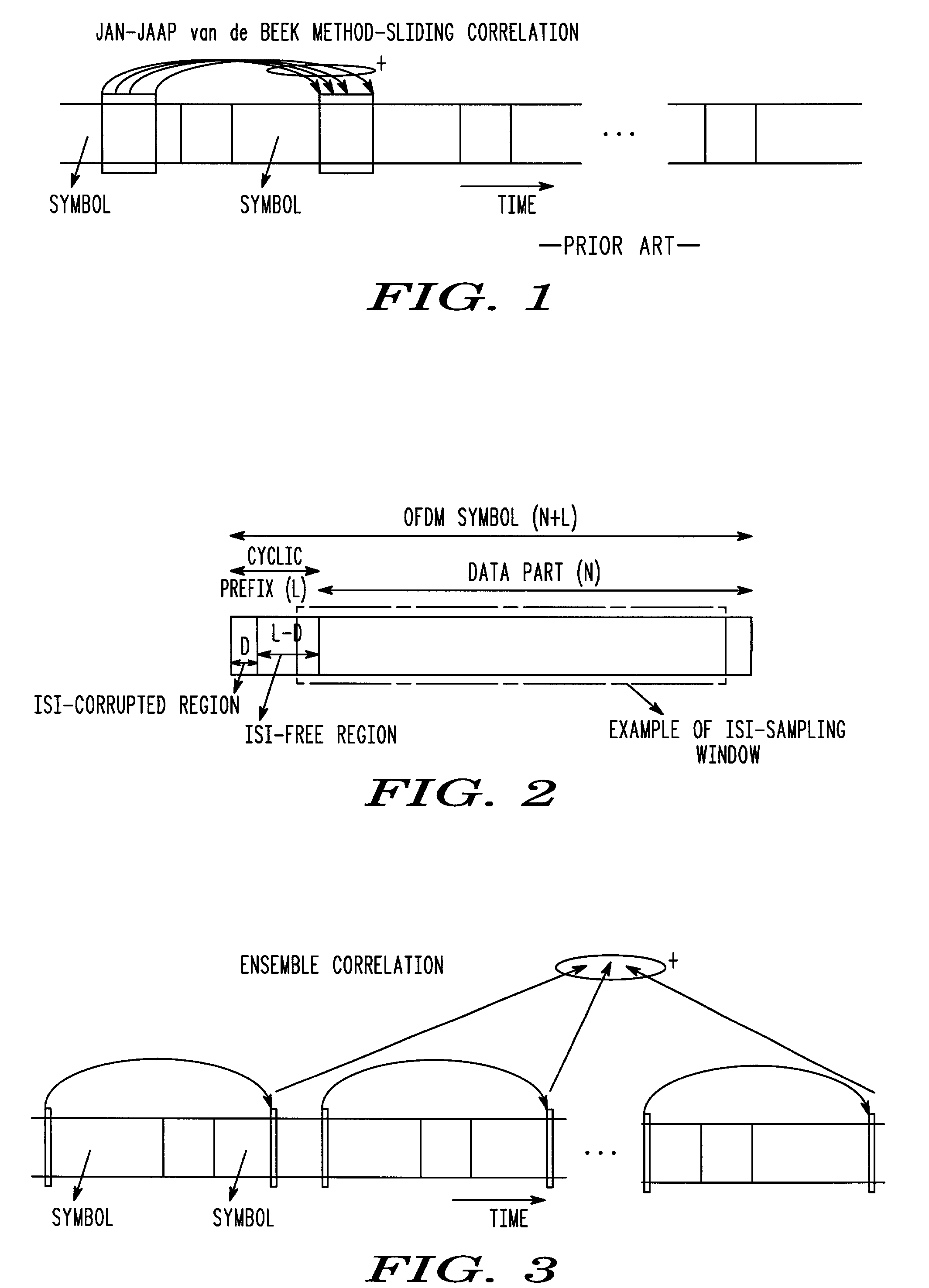
Unfortunately, this method is optimized and well suited for a single-ray channel.
As a consequence, in a multipath-fading channel, the sampling position picked by this method may not be free of ISI and it can waver depending on which of the multipath rays is the strongest at a particular time.
A disadvantage of this method is that the sampling position picked by this method can jump about within a set of valid positions, leading to jitter in the timing estimates.
The jitter makes it difficult to use averaging, e.g., a phase locked loop (PLL), to obtain a steady sampling position.
Another disadvantage with this method is that the timing estimate is based on the training symbol alone and there is no averaging over the fading process.
This creates problems in a fast fading scenario where the instantaneous delay profile at the training symbol could be significantly different from the actual channel power delay profile.
Further, the above mentioned methods are not necessarily intended to provide an estimate of the delay-spread in the channel.

Method used


Image

  • Method and system for timing recovery and delay spread estimation in a communication system
  • Method and system for timing recovery and delay spread estimation in a communication system
  • Method and system for timing recovery and delay spread estimation in a communication system

Examples


Embodiment Construction

)

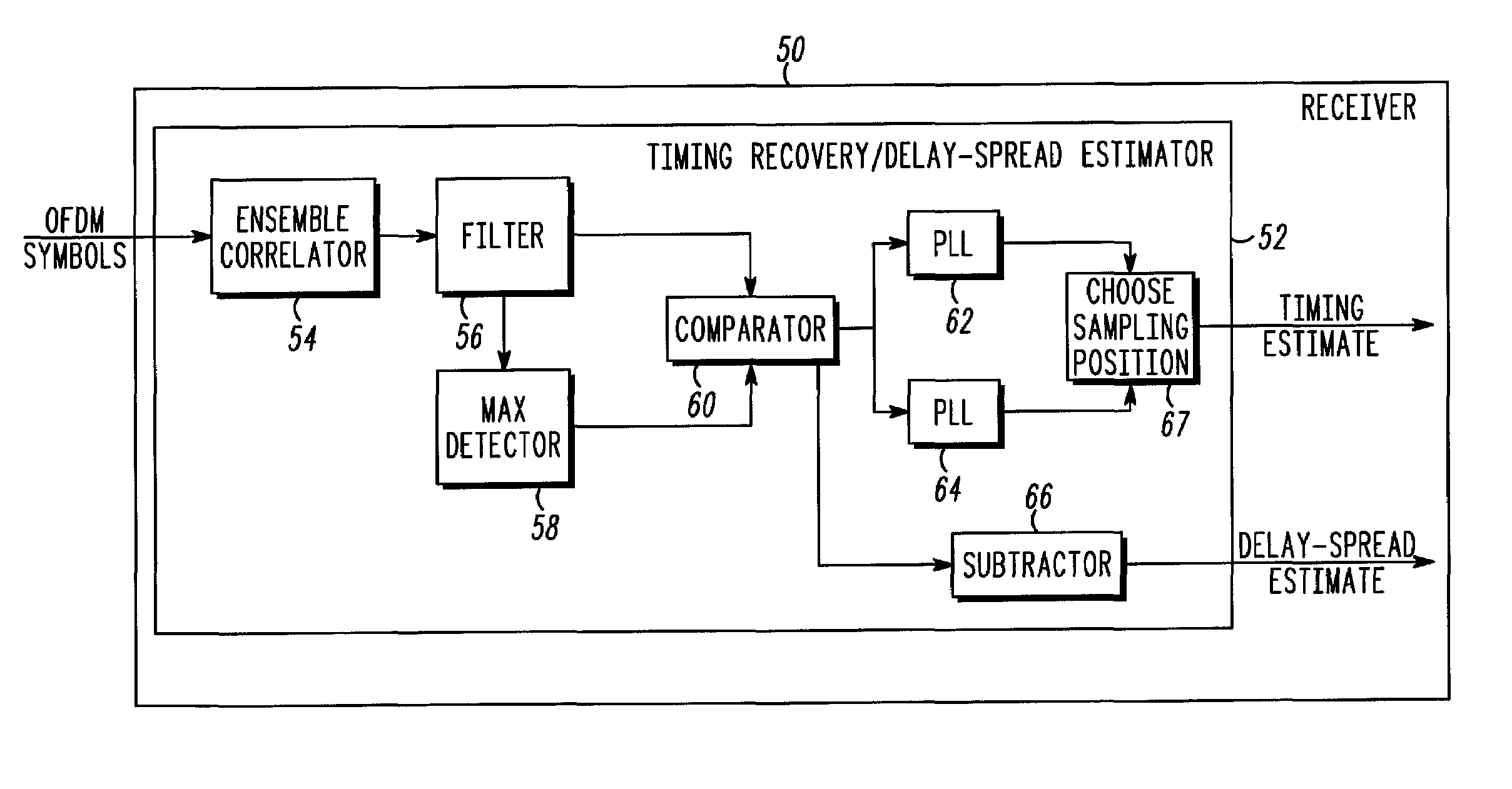
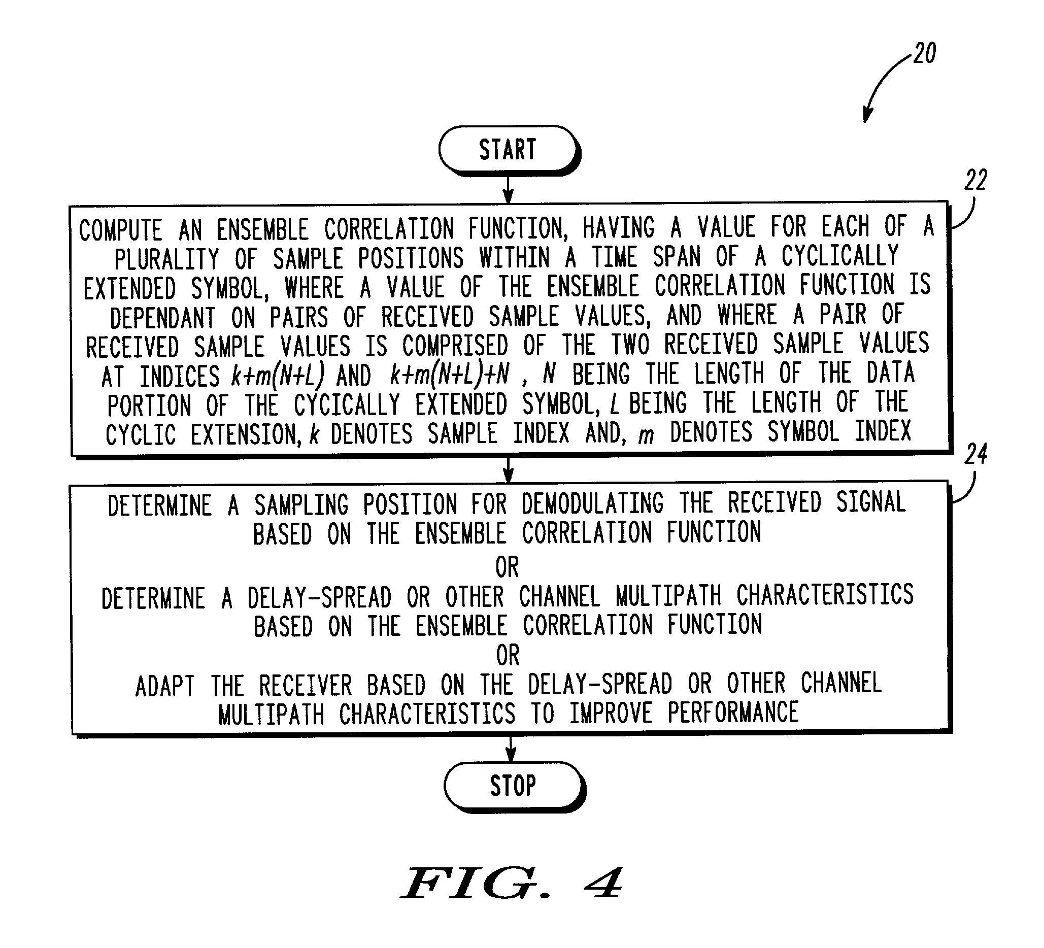
[0017]According to one aspect of the present invention, a timing recovery scheme is provided that demarcates a complete range of ISI-free sampling positions available in an OFDM symbol. Also provided is a method for estimating the multipath delay-spread in the channel, or other multipath channel characteristics. An estimate of one or more multipath channel characteristics, such as delay-spread for example, provides a receiver valuable information about the nature of the channel. The receiver can use this information to adapt the receiver, for example, to adjust the frequency-domain channel interpolation filter bandwidth in order to improve performance for the given channel condition.

[0018]FIG. 2 shows an exemplary OFDM symbol with cyclic prefix partly corrupted by ISI and the range of ISI-free sampling-window positions available for that symbol. As shown, the length of the OFDM symbol is represented by N+L, where the data part length is N and the cyclic prefix length is L; the leng...


PUM


Abstract

A timing recovery scheme demarcates a complete range of inter-symbol interference free (ISI-free) sampling positions available in a cyclically extended symbol. The timing recovery scheme computes an ensemble correlation between the cyclic extension and the data part of symbols to estimate timing. The ensemble correlation function retains delay-spread and timing information by separately maintaining the correlation value for each sample position within the symbol duration and combines the correlation values for identical sample positions over an ensemble of symbols. In this manner, the scheme not only provides timing estimates, but can also provide estimates of the multipath delay-spread in a channel. The delay-spread estimates provide valuable information about the nature of the channel. A receiver can use this information, for example, to adjust the frequency-domain channel interpolation filter bandwidth in order to improve performance for the given channel condition.

Description

[0001]This application claims the benefit of U.S. Provisional Application No. 60 / 414,527, filed Dec. 29, 2000.TECHNICAL FIELD OF THE INVENTION[0002]The present invention relates generally to communication systems, and in particular, to a timing recovery and delay-spread estimation scheme for communication systems that employ cyclically extended symbols.BACKGROUND OF THE INVENTION[0003]Timing recovery in communication systems is related to the process of identifying symbol boundaries in a received signal, so that each symbol can be windowed and processed separately so that its value can be determined. In some communication systems such as OFDM (other examples include IFDMA, Single Carrier with cyclic extension), a guard interval is inserted between successive symbols to overcome inter-symbol interference (ISI) caused by multipath delay-spread in the communication channel. Usually each symbol is cyclically extended with a prefix and / or a postfix to cover the guard interval. The cyclic...

Claims


Application Information

Patent Timeline
IPC IPC(8): H04L27/06H04L27/28H04L25/02H04L27/26
CPCH04L25/0216H04L27/2662H04L27/2676H04L25/022H04L25/0238H04L27/2647
Inventor RAMASUBRAMANIAN, KARTHIKBAUM, KEVIN LYNN
Owner GOOGLE TECH HLDG LLC
Learn More