Disk player

a technology of a disk player and a clamper, which is applied in the field of disk players, can solve the problem that the inserted card is not capable of moving the transfer roller, and achieve the effect of preventing the bending of the clamper

Inactive Publication Date: 2006-11-07
SANYO ELECTRIC CO LTD +1
View PDF11 Cites 13 Cited by
  • Summary
  • Abstract
  • Description
  • Claims
  • Application Information

AI Technical Summary

Benefits of technology

[0014]In the first configuration, preferably, the clamper is provided in such a manner as to be lifted or descended by the clamp mechanism with a rear-end portion thereof serving as a supporting point, and the rear-end portion is configured in such a manner as to engage with engaging holes which allow upward and downward movements of the rear-end portion. According thereto, when the clamper is further pushed upwardly after being lifted and abuts against an upper plate of a chassis, the rear-end portion can move (run off) upwardly in the engaging holes, which can prevent bending of the clamper.

Problems solved by technology

Therefore, the inserted card is not capable of moving the transfer roller.

Method used


Image

  • Disk player
  • Disk player
  • Disk player

Examples


Embodiment Construction

[0052]Hereinafter, an embodiment of the present invention will be described based on FIGS. 1 to 13.

(General Outline of Disk Player)

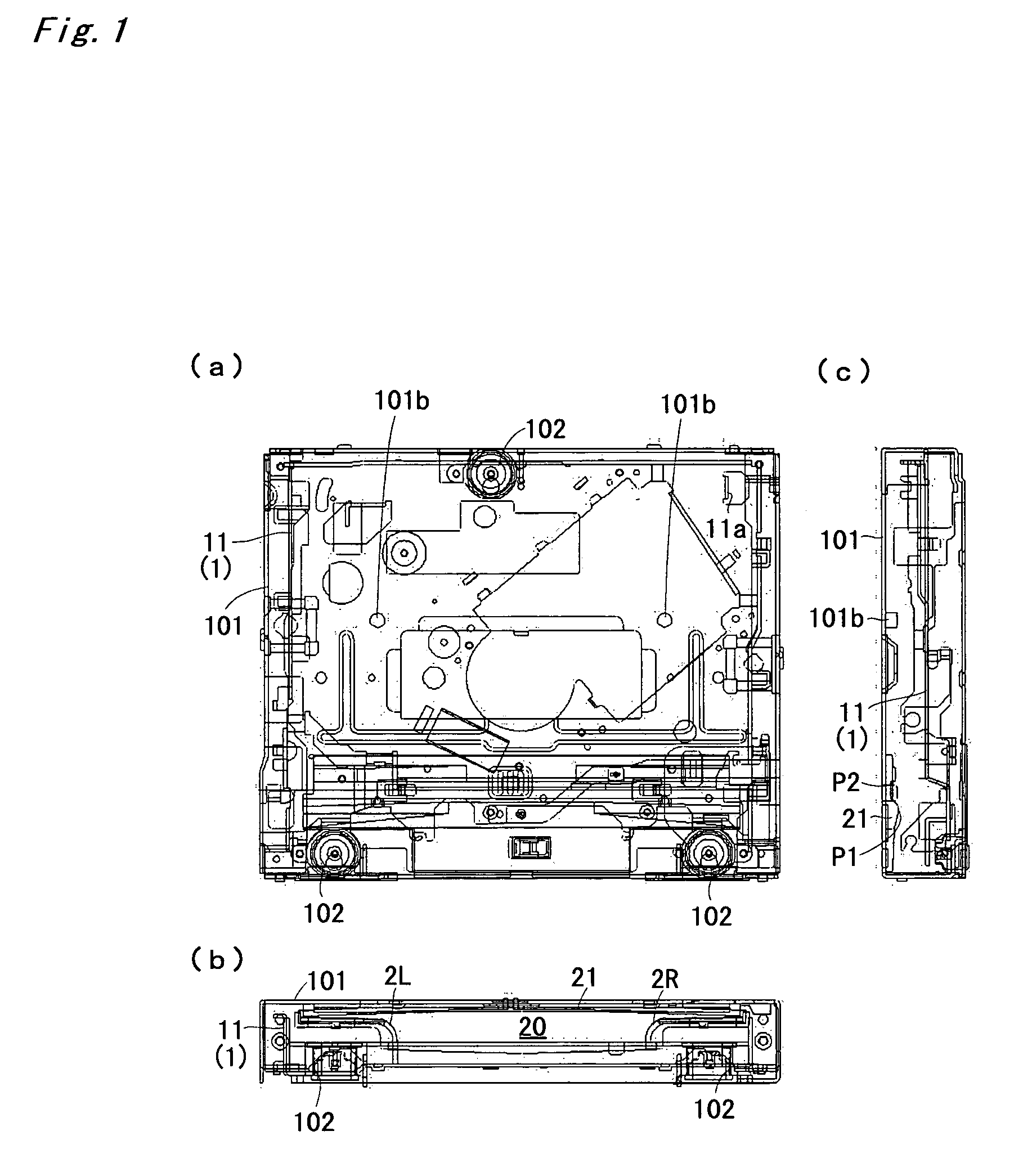
[0053]FIG. 1 illustrates a disk player (chassis portion), wherein representation of various types of driving mechanisms is omitted. FIG. 1(a) is a plan view, FIG. 1(b) is a front view and FIG. 1(c) is a right side view. A disk player main body 1 (a main body chassis 11 is illustrated in FIG. 1) is provided within a chassis base 1101. The main body chassis 11 is elastically supported by coil spring clampers 102 (which are placed at three positions) provided on a lower-surface side of the main-body chassis 11, within the chassis base 101. A disk loading slit 20 is formed in a front surface of the chassis base 101. The disk loading slit 20 is provided with a right disk guide 2R and a left disk guide 2L formed from resin, and the disk loading slit 20 has a shape similar to a T-shape. The distance between the right end of the upper surface of the right disk g...


PUM

PropertyMeasurementUnit
driving poweraaaaaaaaaa
diameteraaaaaaaaaa
forceaaaaaaaaaa

Abstract

A restriction plate (21) is provided on a lower surface of a near side of an upper plate of a chassis base (101). Both disk (D1) and disk (D2), while keeping in contact with a contact guide portion P1 of the restriction plate (21), are inserted. A stopper portion (P2) is formed at a farther side position than the contact guide portion (P1). A peripheral surface of a transfer roller (5) is placed in a moving direction of the disks (D1), (D2) proceeding while contacting upper surfaces of disk guides (2R), (2L) of a disk loading slit (20), and the contact guide portion (P1). Further, the stopper portion (P2) exists at a position corresponding to a direction of a tangent line which passes through the contact guide portion (P1), out of the tangent lines of the aforementioned peripheral surface, at positions other than the moving direction of the disks (D1), (D2).

Description

TECHNICAL FIELD[0001]The present invention relates to a disk player for reproducing a disk (recording medium) such as a CD or a DVD, and others.BACKGROUND ART[0002]Conventionally, portable-type disk players and vehicle-mounted type disk players have been proposed. In recent years, there have been proposed disk players capable of reproducing both an 8-cm disk and a 12-cm disk (see JP-A 2001-143352). Further, there have been proposed disk players capable of reproducing a DVD, as well as a CD.[0003]In such the disk players, there is a need for a mechanism to prevent foreign substances such as a telephone card, and others, from being inserted into a player main body.[0004]Further, in such the disk players, during ejecting, an operation for raising a clamper for clamping the disk is performed, and in a case that the clamper is positioned by abutting a tip-end side (a portion raised most highly) of the clamper against a chassis upper plate, the clamper, if a force of the abutment is large...

Claims


Application Information

Patent Timeline
Patent Type & Authority Patents(United States)
IPC IPC(8): G11B17/04G11B17/028G11B17/051G11B17/03
CPCG11B17/0284G11B17/0288G11B17/0404G11B17/0515G11B17/04G11B17/02G11B17/028
Inventor AOKI, SHINICHIHASEGAWA, YOSHIKAZUHOKIMOTO, YUKINORI
Owner SANYO ELECTRIC CO LTD
Why Eureka
Try Eureka