Disc valve

a technology of disc valves and valves, applied in the direction of multiple way valves, valve arrangements, thin material handling, etc., can solve the problems of poor maneuverability of disk valves, and achieve the effect of reducing oil dispersion and maintaining high maneuverability

Inactive Publication Date: 2006-11-14
TOTO LTD
View PDF14 Cites 47 Cited by
  • Summary
  • Abstract
  • Description
  • Claims
  • Application Information

AI Technical Summary

Benefits of technology

[0006]An object of the present invention is to provide a disk valve comprising an inlet port, an outlet port, a first disk provided with a first through hole communicating with the inlet port and extending axially and a second through hole communicating with the outlet port and extending axially, and a second disk provided with a concave capable of communicating with the first through hole and the second through hole of the first disk on one end face and slidably and movably contacting one end face of the first disk at the one end face, wherein a closed space is formed radially outside the second disk, and the second disk slides relative to the first disk to adjust the degree of overlap between the concave of the second disk and the first through hole of the first disk, and wherein dispersion of the oil into the discharging water is suppressed and good maneuverability is maintained for a long time.

Problems solved by technology

The conventional disk valves have a disadvantage in that oil adhered to the slidably and movably contacting part is carried away by water flowing from the first through hole of the first disk to the second through hole of the first disk through the concave of the second disk to slightly disperse into water discharging from the disk valve, thereby gradually being diminished to cause poor maneuverability of the disk valves.

Method used


Image

  • Disc valve
  • Disc valve
  • Disc valve

Examples


Embodiment Construction

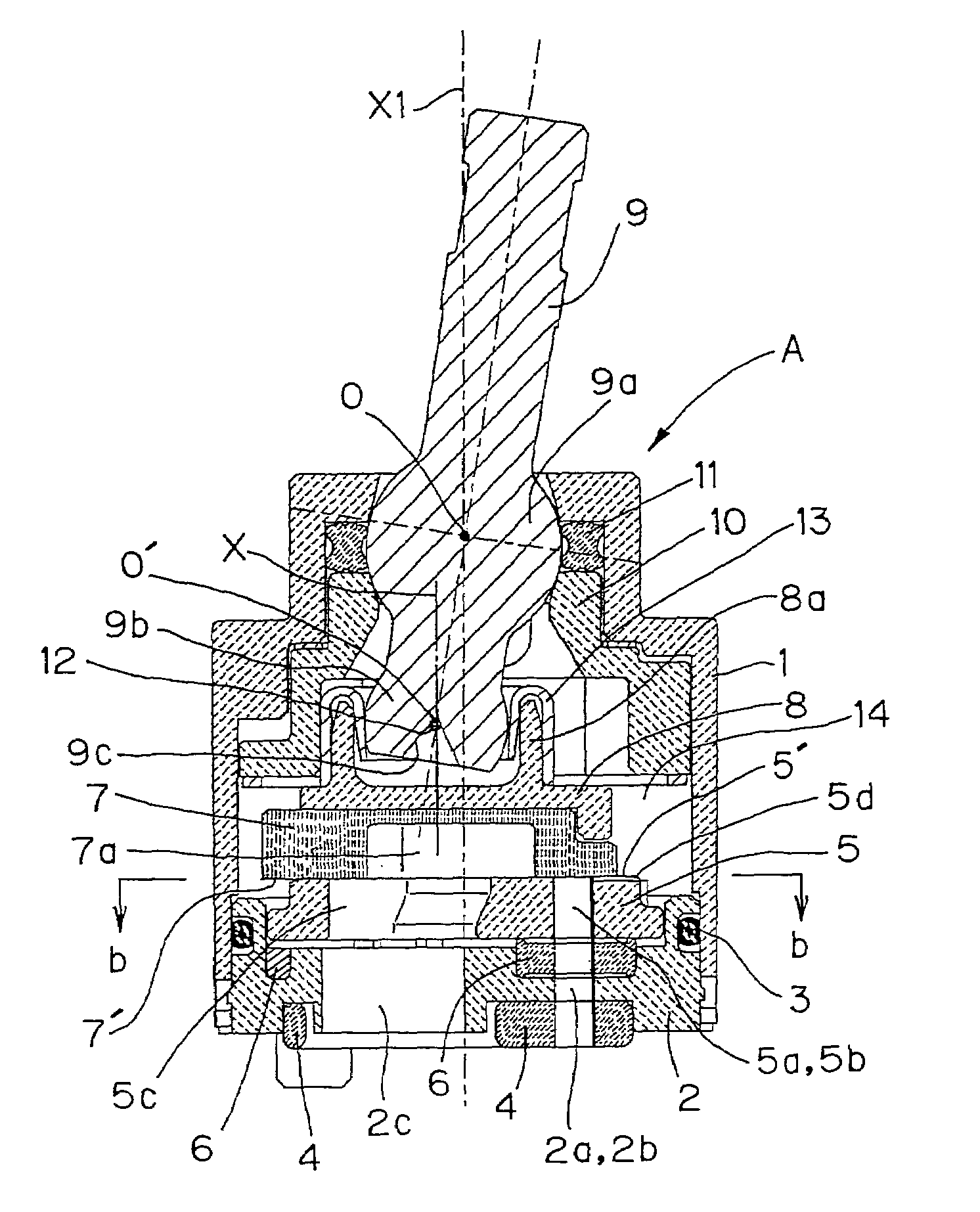
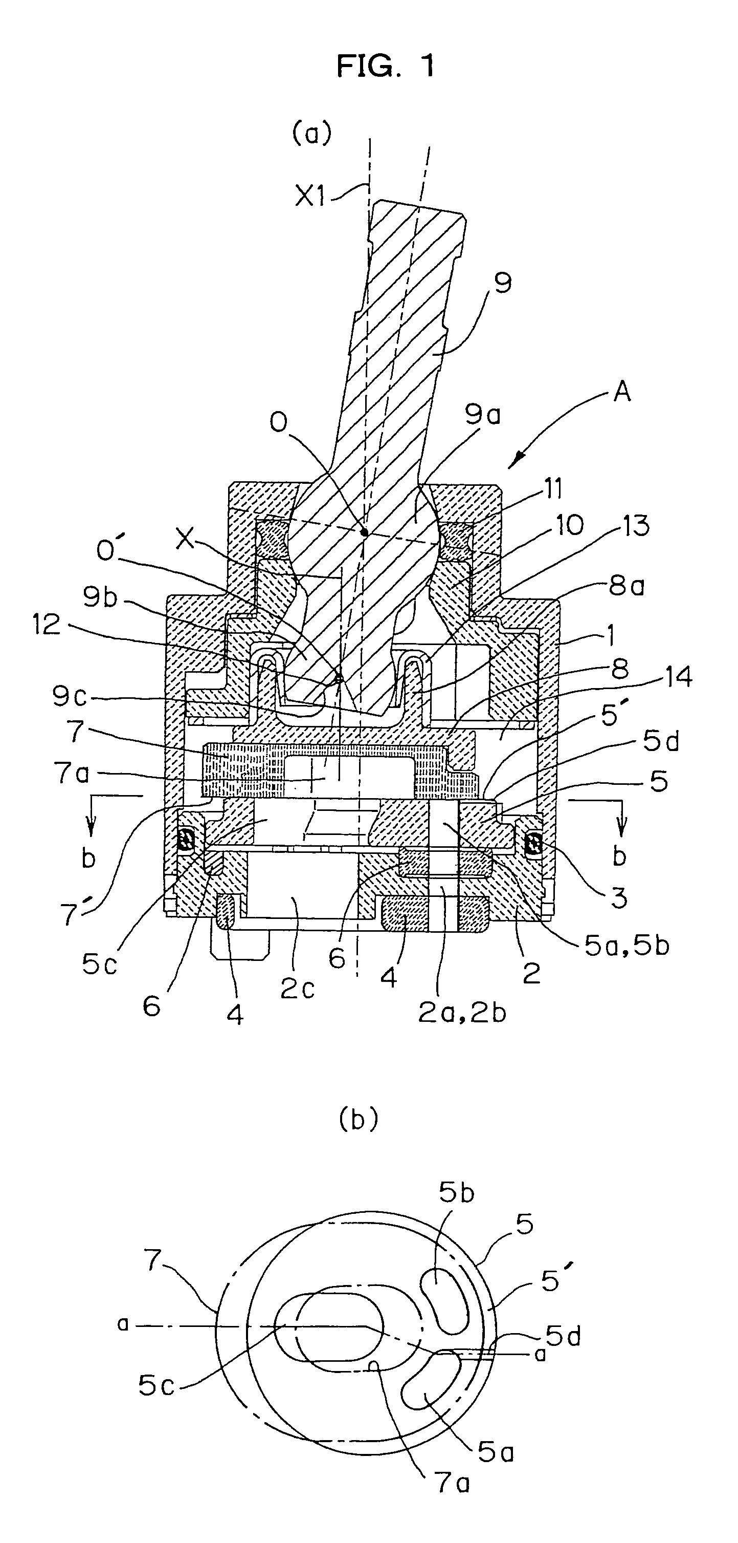
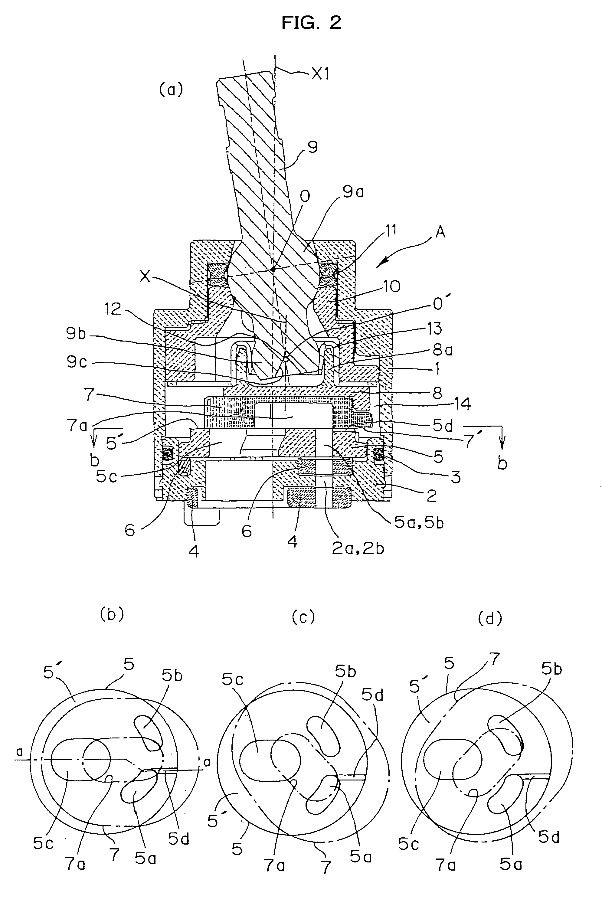
[0033]A disk valve in accordance with the first preferred embodiment of the present invention will be described.

[0034]As shown in FIGS. 1 and 2, a disk valve A comprises a cylindrical cartridge case 1 made of synthetic resin and provided with a large diameter portion and a small diameter portion, and a disk-shaped packing guide 2 made of synthetic resin and fitted in and fixed to the end of the large diameter portion of the cartridge case 1. An O-ring 3 seals the contacting part between the inner circumferential surface of the cartridge case 1 and the outer circumferential surface of the packing guide 2. A hot water inlet port 2a, a cool water inlet port 2b and a mixed water outlet port 2c are formed in the packing guide 2 independently of each other to penetrate the packing guide 2 axially. A gasket 4 is fitted in the packing guide 2 to seal the connections between the hot water inlet port 2a, the cool water inlet port 2b, the mixed water outlet port 2c and a hot water inlet port, ...


PUM


Abstract

A disk valve comprises an inlet port, an outlet port, a first disk provided with a first through hole communicating with the inlet port and extending axially and a second through hole communicating with the outlet port and extending axially, and a second disk provided with a concave capable of communicating with the first through hole and the second through hole of the first disk on one end face and slidably and movably contacting one end face of the first disk at the one end face. A closed space is formed radially outside the second disk, and the second disk slides relative to the first disk to adjust the degree of overlap between the concave of the second disk and the first through hole of the first disk. The slidably and movably contacting part between the first disk and the second disk is self-lubricated. The disk valve further comprises a communication passage for always placing the first through hole into communication with the closed space radially outside the second disk. A portion of the one end face of the first disk adjacent to the part slidably and movably contacting the second disk opposes the closed space

Description

[0001]This is a National Phase Application in the United States of International Patent Application No. PCT / JP02,08345, filed Aug. 19, 2002, the entire disclosure of which is hereby incorporated by reference.TECHNICAL FIELD[0002]The present invention relates to a disk valve suitable for use in single lever water combination faucets, water faucets, or the like.BACKGROUND ART[0003]There have been used disk valves for single lever water combination faucets, water faucets, or the like, comprising an inlet port, an outlet port, a first disk provided with a first through hole communicating with the inlet port and extending axially and a second through hole communicating with the outlet port and extending axially, and a second disk provided with a concave capable of communicating with the first through hole and the second through hole of the first disk on one end face and slidably and movably contacting one end face of the first disk at the one end face, wherein a closed space is formed ra...

Claims


Application Information

Patent Timeline
Patent Type & Authority Patents(United States)
IPC IPC(8): F16K11/074F16K11/078
CPCF16K11/0787Y10T137/86823
Inventor HIROSHI, OHSHIMATAKAHIRO, TANIGUCHI
Owner TOTO LTD
Why Eureka
Try Eureka