Fluidic oscillator and method

Active Publication Date: 2006-11-14
DLHBOWLES INC
View PDF7 Cites 18 Cited by
  • Summary
  • Abstract
  • Description
  • Claims
  • Application Information

AI Technical Summary

Benefits of technology

[0003]In Bauer U.S. Pat. No. 4,184,636, a fluidic oscillator is disclosed which includes a chamber having a common inlet and outlet opening for which the fluid power jet is issued across the chamber. The jet impinges on a reversing wall and splits and turns so that each turned half exits through an opposite outlet port. This flow pattern contains two oppositely rotating vortices and is inherently unstable in that any small dissimilarity in the flow will abet one side while deterr

Problems solved by technology

This flow pattern contains two oppositely rotating vortices and is inherently unstable in that any small dissimilarity in the flow will abet one side while deterring the other

Method used


Image

  • Fluidic oscillator and method
  • Fluidic oscillator and method
  • Fluidic oscillator and method

Examples


Embodiment Construction

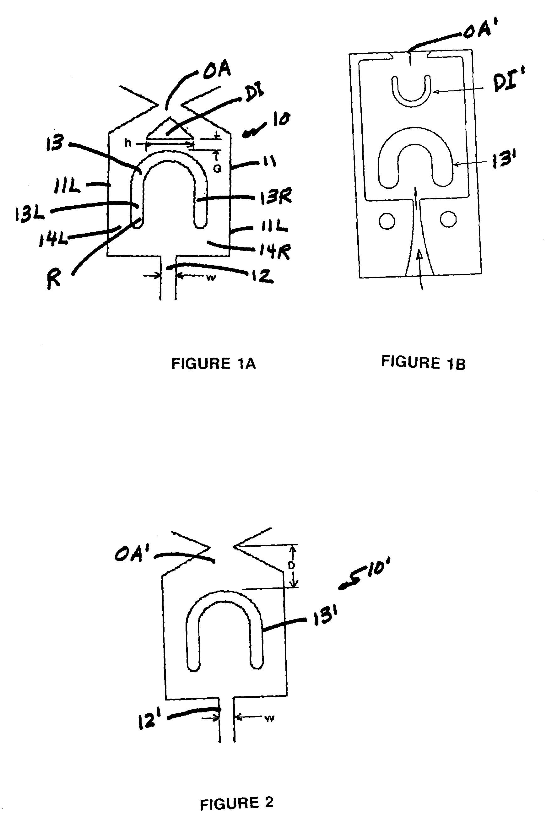
[0015]Referring now to FIG. 1A, a fluidic oscillator 10 incorporating the invention is shown in silhouette form and incorporates an oscillation chamber 11 having a power nozzle 12 with a width W. The power nozzle 12 projects a jet of liquid into the oscillation chamber 11. A U-shaped reversing member 13 has its legs 13L and 13R spaced from the sidewalls 11L, 11R. The radius R of the legs 13L and 13R of U-shaped reversing member 13 is such as to not impede the reversing output flows to passageways 14R and 14L (see FIG. 4D). The design as illustrated is such as to preclude the formation of a counteracting vortex which would stop the oscillation. It has been found that providing a generous space for the turning or reversing radius R while properly sizing the cross-section of the passageways 14L, 14R does not impede the oscillation.

[0016]The oscillation operating mechanism is illustrated in FIGS. 4A, 4B and 4C which are progressive stages of the cycle. FIG. 4A shows the oscillator in on...


PUM


Abstract

An oscillating spray device comprising an oscillation chamber. A power nozzle for projecting a jet of liquid under pressure into the oscillation chamber in a given direction. A reversing member in the chamber has a reversing wall for reversing the direction of flow of the fluid jet in a direction 180° opposite the given direction. A system of vortices is formed thereby for alternately passing fluid to one side or the other of the reversing member. A pair of passages, one on each side of the reversing member, convey alternate pulses of fluid through the passageways in the given direction past the reversing member to an outlet to ambient, and an island barrier positioned in the outlet to ambient and forming two separate passageways to the outlet and a third passageway between the reversing member and the island barrier. The spray characteristics can be adjusted by changing the spacing between the reversing member and island barrier.

Description

REFERENCE TO RELATED APPLICATION[0001]The present application is the subject of provisional application No. 60 / 470,492 filed May 15, 2003 and entitled REVERSE-REVERSING CHAMBER OSCILLATING NOZZLE.BACKGROUND AND BRIEF DESCRIPTION OF THE INVENTION[0002]The present invention relates to improvements in fluidic oscillators and novel spray-forming output structures for fluidic oscillators.[0003]In Bauer U.S. Pat. No. 4,184,636, a fluidic oscillator is disclosed which includes a chamber having a common inlet and outlet opening for which the fluid power jet is issued across the chamber. The jet impinges on a reversing wall and splits and turns so that each turned half exits through an opposite outlet port. This flow pattern contains two oppositely rotating vortices and is inherently unstable in that any small dissimilarity in the flow will abet one side while deterring the other side so that one vortex dominates the opposite or other vortex to the point where all the flow exits the one outp...

Claims


Application Information

Patent Timeline
IPC IPC(8): B05B3/00B05B1/08B05B1/14B05B15/08B05B15/68
CPCB05B1/08
Inventor STOUFFER, RONALD D.SANTAMARINA, ALAND
Owner DLHBOWLES INC
Why Eureka
Try Eureka