Tunable fluid flow control system

a fluid flow control and fluid flow control technology, applied in the direction of liquid/fluent solid measurement, lighting and heating apparatus, instruments, etc., can solve the problems of system dynamic response, flame stability, noise, etc., and achieve the effect of reducing the number of lpc systems

Inactive Publication Date: 2011-01-13
GENERAL ELECTRIC CO
View PDF9 Cites 13 Cited by
  • Summary
  • Abstract
  • Description
  • Claims
  • Application Information

AI Technical Summary

Benefits of technology

[0005]Accordingly, there is a need for tunable fluid flow control system.
[0006]In accordance with one exemplary embodiment of the present invention, a tunable fluid flow control system is disclosed. The control system includes a fluidic oscillator having a movable boundary wall. A pressurized gas source is coupled to the movable boundary wall and configured to supply a stream of pressurized gas to the movable boundary wall to actuate the boundary wall. The boundary wall is actuatable to vary a cavity volume in the fluidic oscillator so as to control frequency of flow of a pulsating fluid through the fluidic oscillator. A portion of a fluid is bypassed the fluidic oscillator so as to control amplitude of flow of a pulsating fluid generated by the fluidic oscillator.
[0007]In accordance with another exemplary embodiment of the present invention, a tunable fuel flow control system for controlling combustion in at least one combustor is disclosed.
[0008]In accordance with another exemplary embodiment of the present invention, a tunable fluid flow control system for controlling drag of at least one fluid boundary layer is discl

Problems solved by technology

LPC systems can have problems with flame stability, noise, and can exhibit system dynamic responses (combustion instabilities).
Combustion dynamics (or instability) is well known problem encountered by the lean premixed combustion systems leading to operational restrictions and even to potential hardware downtime.
However, the mechanically actuated systems have the drawbacks that the characteristic response frequency a

Method used


Image

  • Tunable fluid flow control system
  • Tunable fluid flow control system
  • Tunable fluid flow control system

Examples


Embodiment Construction

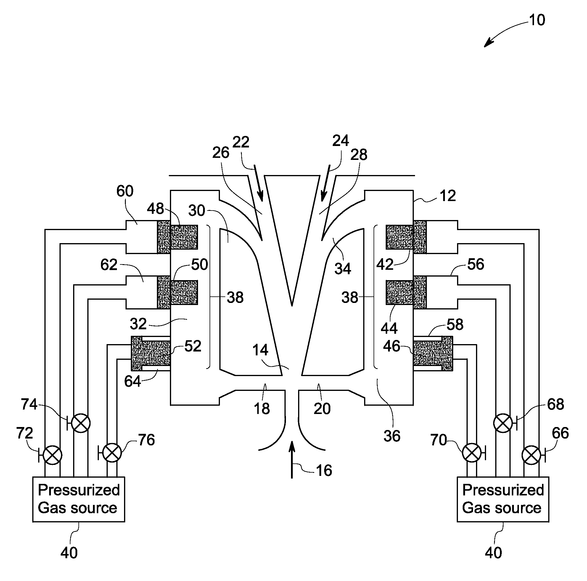
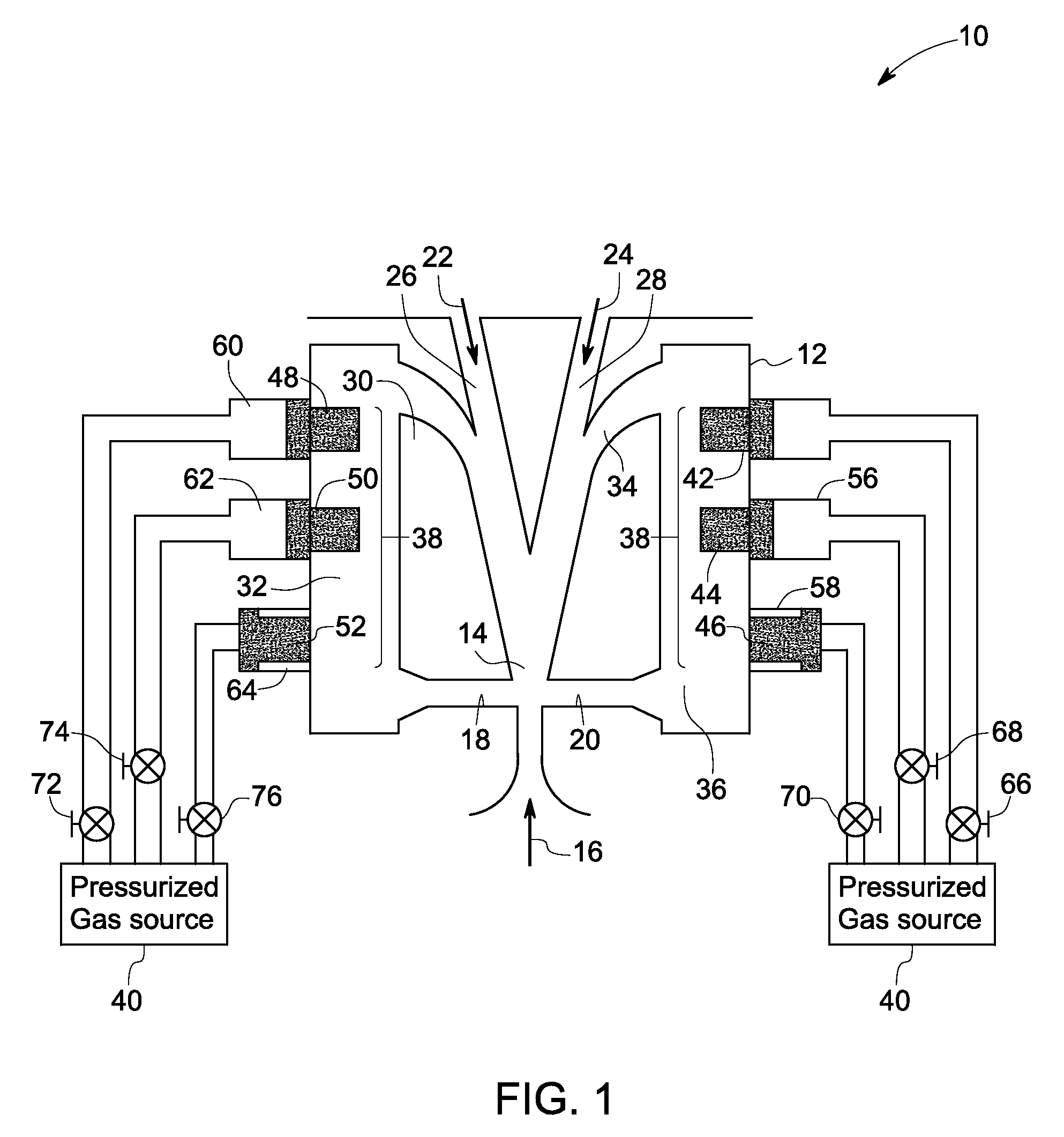
[0019]As discussed in detail below, certain embodiments of the present invention discloses a tunable fluid flow control system having a fluidic oscillator. The fluidic oscillator includes a movable boundary wall. A pressurized gas source is coupled to the movable boundary wall and configured to supply a stream of pressurized gas to the movable boundary wall to actuate the boundary wall. The boundary wall is actuatable to vary a cavity volume in the fluidic oscillator so as to control frequency of flow of a pulsating fluid through the fluidic oscillator. A portion of a fluid is bypassed the fluidic oscillator so as to control amplitude of flow of a pulsating fluid generated by the fluidic oscillator. In accordance with some embodiments of the present invention, a tunable fluidic oscillator supplies a pulsating fluid stream to a target of interest at a frequency, amplitude, or combinations thereof chosen by an operator using the control system. In accordance with certain other embodim...


PUM


Abstract

A tunable fluid flow control system includes a fluidic oscillator having a movable boundary wall. A pressurized gas source is coupled to the movable boundary wall and configured to supply a stream of pressurized gas to the movable boundary wall to actuate the boundary wall. The boundary wall is actuatable to vary a cavity volume in the fluidic oscillator so as to control frequency of flow of a pulsating fluid generated by the fluidic oscillator. A portion of a fluid is bypassed the fluidic oscillator so as to control amplitude of flow of a pulsating fluid generated by the fluidic oscillator.

Description

BACKGROUND[0001]The invention relates generally to tunable fluid flow control system, and more particularly to a tunable fluidic oscillator for controlling dynamic pressure variations in a combustor, drag of a fluid boundary layer, or combinations thereof.[0002]In one application involving combustion, lean premixed combustion (LPC) is currently one of the most promising concepts for substantial reduction of emissions while maintaining high efficiency for gas turbine combustors. This mode of combustion is operated with excess air to reduce flame temperatures in combustors to acceptable levels typically less than 1800 Kelvin. At these flame temperatures, the production of thermal NOX (oxides of nitrogen) is virtually eliminated; and the production of prompt NOX is negligible. This intrinsic benefit can be offset by several potential disadvantages. LPC systems can have problems with flame stability, noise, and can exhibit system dynamic responses (combustion instabilities).[0003]Combus...

Claims


Application Information

Patent Timeline
IPC IPC(8): G01F1/20
CPCF23D2900/14482F23K2900/05001F23N1/002F23R2900/00013F23N2025/04F23R3/286F23R2900/00001F23N5/242F23N2225/04
Inventor HAYNES, JOEL MEIERCERRETELLI, CIRO
Owner GENERAL ELECTRIC CO
Why Eureka
Try Eureka