Switching power supply control circuit
A switching power supply and control circuit technology, applied in the direction of electrical components, output power conversion devices, etc., can solve the problems of adjustment control and impossibility, and achieve the effect of improving poor dynamic characteristics
- Summary
- Abstract
- Description
- Claims
- Application Information
AI Technical Summary
Problems solved by technology
Method used
Image
Examples
no. 1 example
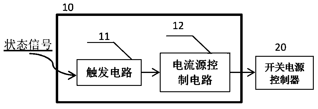
[0039] The LLC resonant converter is a typical current-controlled switching power supply. In the design of the LLC resonant converter, the designer generally knows that the higher the frequency of the circuit during the start-up process of the converter, the better. In this case, the high-resistance characteristics exhibited will suppress the large inrush current generated by the action of the semiconductor switching device on the resonant cavity during the start-up process of the converter, and furthermore, it will also reduce the large voltage stress generated at both ends of the resonant capacitor . Obviously, if the operating frequency of the converter is not increased at start-up, power supply designers often choose switching transistors with larger current margins and film capacitors with higher withstand voltage values for the design of LLC resonant converters. However, high-current switching transistors and high-voltage film capacitors also mean increased design cost...
no. 2 example
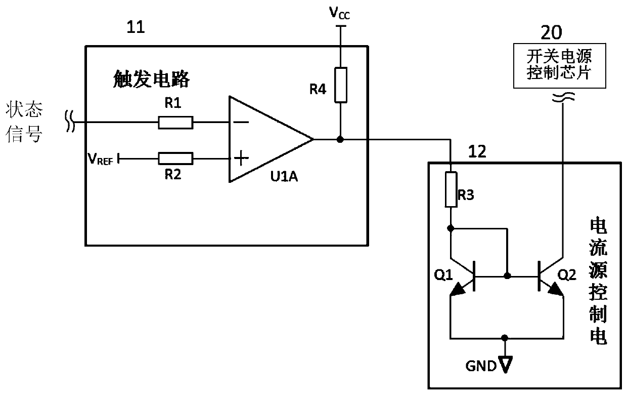
[0063] Such as Figure 4 As shown, it is a functional block diagram of the second embodiment of the present invention, which is different from the first embodiment in that a resistor R5 is added to the trigger circuit 11 . One end of the resistor R5 is used to connect the bus voltage V of the LLC resonant converter input BUS , the other end of the resistor R5 is connected to the output end of the comparator U1A. Here, the working principle of controlling the frequency during startup of the LLC resonant converter is the same as that of the first embodiment, and will not be repeated here. Only the changes in the principle of the circuit brought about by adding the resistor R5 are described.
[0064] The output pull-up resistors R4 and R5 of the comparator U1A are respectively connected to a constant voltage V CC The bus voltage V of the LLC resonant converter BUS . Since the output terminal of the comparator U1A is connected to the bus voltage through the resistor R5, it pr...
no. 3 example
[0067] Such as Figure 5 As shown, it is the functional block diagram of the third embodiment of the present invention. The difference from the second embodiment is that the trigger circuit 11 also adds a diode D1, a diode D2 and a resistor R6; the anode of the diode D1 is connected to the bus voltage V of the LLC resonant converter BUS , the cathode of the diode D1 is connected to one end of the resistor R5, and the other end of the resistor R5 is connected to the output end of the comparator U1A. The anode of diode D2 is connected to the voltage signal V converted by temperature change TMP, the cathode of the diode D2 is connected to one end of the resistor R6, and the other end of the resistor R6 is connected to the output end of the comparator U1A. Here, the working principle of controlling the frequency during the start-up of the LLC resonant converter is still the same as that of the first embodiment, and will not be repeated here. Only the changes in the principle of ...
PUM
 Abstract
Description
Claims
Application Information
 - R&D
- Intellectual Property
- Life Sciences
- Materials
- Tech Scout
- Unparalleled Data Quality
- Higher Quality Content
- 60% Fewer Hallucinations
Browse by: Latest US Patents, China's latest patents, Technical Efficacy Thesaurus, Application Domain, Technology Topic, Popular Technical Reports.
© 2025 PatSnap. All rights reserved.Legal|Privacy policy|Modern Slavery Act Transparency Statement|Sitemap|About US| Contact US: help@patsnap.com


