Electrostatic precipitator wash system

a precipitator and electrostatic technology, applied in the direction of electrode cleaning, liquid cleaning, chemistry apparatus and processes, etc., can solve the problems of inefficient and laborious, inefficient and laborious detergent and energy to heat water, and significant business expense of detergent and energy to clean water, so as to improve the transfer of kinetic and thermal energy, the effect of efficient operation

a precipitator and electrostatic technology, applied in the direction of electrode cleaning, liquid cleaning, chemistry apparatus and processes, etc., can solve the problems of inefficient and laborious, inefficient and laborious detergent and energy to heat water, and significant business expense of detergent and energy to clean water, so as to improve the transfer of kinetic and thermal energy, the effect of efficient operation

US20070240742A1Inactive Publication Date: 2007-10-18ILLINOIS TOOL WORKS INC

Image

  • Electrostatic precipitator wash system
  • Electrostatic precipitator wash system
  • Electrostatic precipitator wash system

Examples


Embodiment Construction

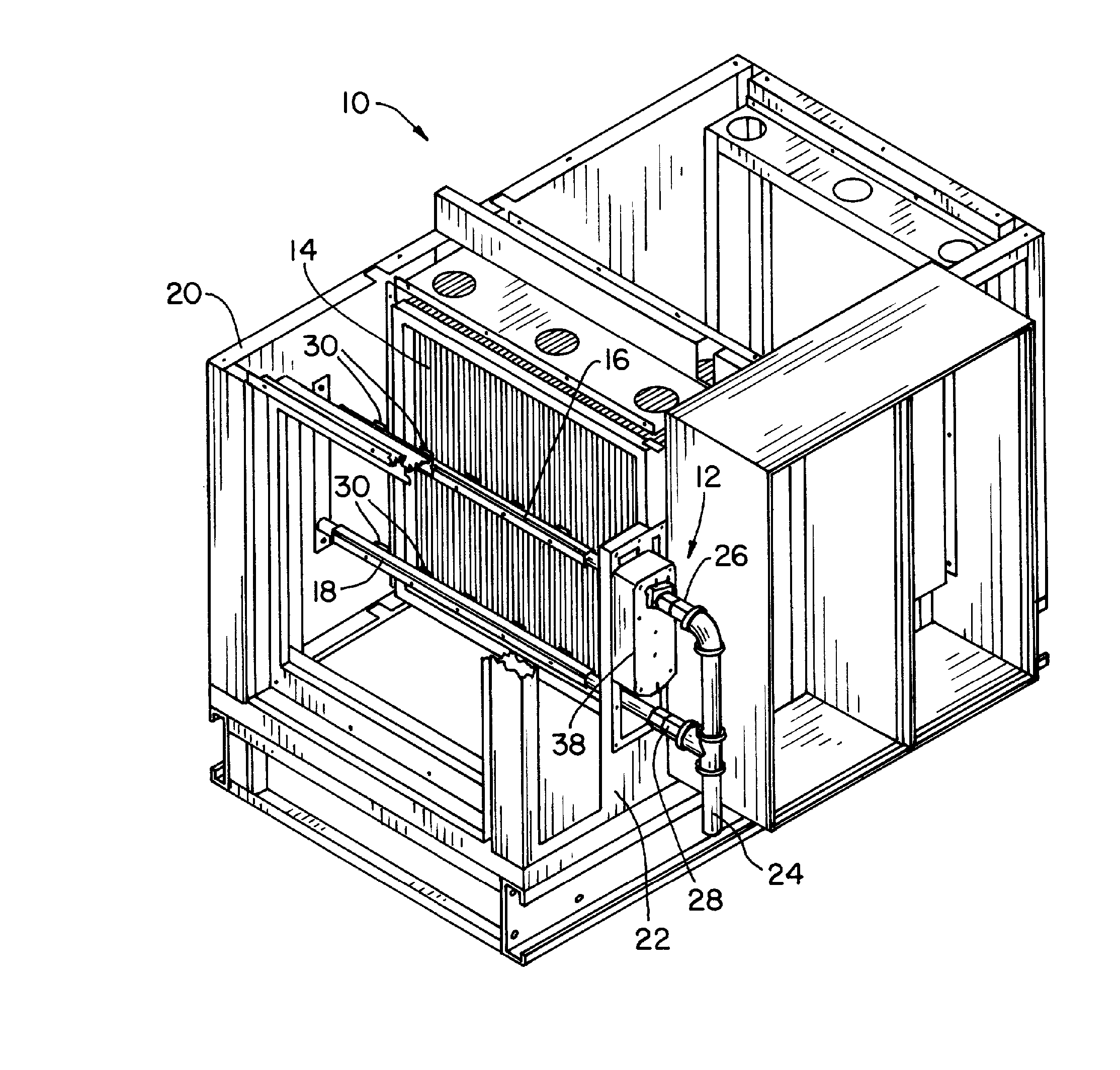
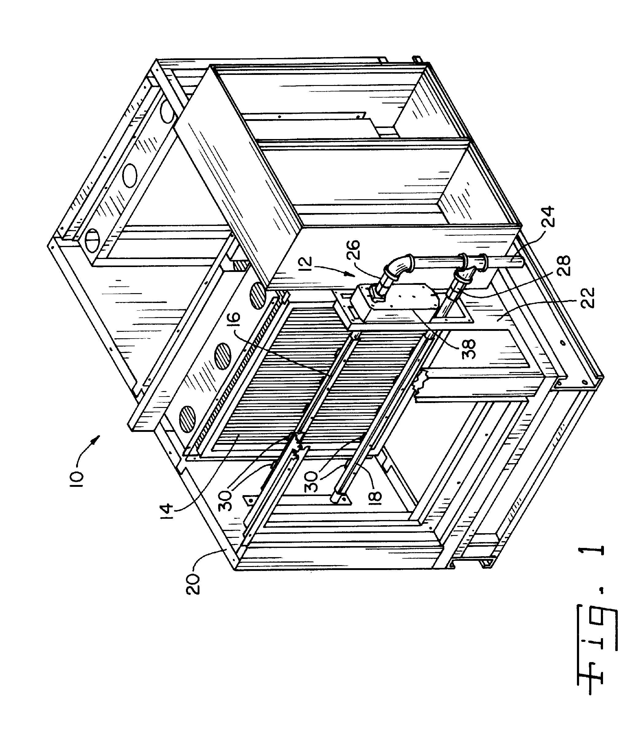
[0030] Referring now more specifically to the drawings and to FIG. 1 in particular, an electrostatic precipitator 10 having a wash system 12 in accordance with the present invention is shown. Precipitator 10 includes an electrostatic cell 14 through which a stream of exhaust air passes for cleaning, in known manner. The operation of electrostatic precipitator 10 to clean an air stream is known to those skilled in the art and will not be described in further detail herein. Wash system 12 is provided for cleaning cell 14 periodically, to remove accumulated contaminants from surfaces of cell 14. Wash system 12 can be used on different types of electrostatic precipitator cells, and the particular configuration shown for electrostatic precipitator 10 and cell 14 thereof are merely exemplary.

[0031] Wash system 12 includes manifolds 16 and 18 positioned on one side of cell 14, and extending across the face of the cell between side walls 20, 22 at opposite ends. A wash solution supply line...


PUM


Abstract

An electrostatic precipitator wash system includes a plurality of fluidic oscillator nozzles through which wash solution is directed at the electrostatic cell of the electrostatic precipitator. The nozzles are provided in a manifold rotatable about an axis of the manifold. The manifold is rotated through an arc of about 90° while emitting wash solution toward the cell in an oscillating stream of drops.

Description

CROSS-REFERENCE TO RELATED APPLICATIONS [0001] The present regular U.S. Patent Application claims the benefits of U.S. Provisional Application Ser. No. 60 / 815,943, filed on Jun. 23, 2006; and is a continuation-in-part of U.S. patent application Ser. No. 11 / 005,985 filed on Dec. 7, 2004; which is a continuation-in-part of U.S. application Ser. No. 10 / 837,362, filed on May 1, 2004.FIELD OF THE INVENTION [0002] The present invention relates generally to electrostatic precipitators, and, more specifically, to wash systems used to clean electrostatic precipitators used for cleaning exhaust air, such as from kitchens. BACKGROUND OF THE INVENTION [0003] It is known to use electrostatic precipitators to remove particles from air streams before the air is discharged into the atmosphere. For example, electrostatic precipitators are used to clean kitchen exhaust air of grease and other cooking residue and byproducts. It is known to use different screens, filters and other air cleaning devices ...

Claims


Application Information

Patent Timeline
18 Oct 2007
Publication
US20070240742A1
IPC
B03C3/74; B08B3/04
CPC
B03C3/78; B03C3/08
Inventors
KWOK, KUI-CHIU; ROBISON, RUSSELL