Bubble generation for aeration and other purposes

a technology for generating bubbles and aeration, which is applied in the direction of flotation, mixing methods, mixers, etc., can solve the problems of less rapid formation, large bubbles, and less air, and achieve the effect of reducing the size of the aperture, and increasing the size of the bubbl

Active Publication Date: 2010-01-07
PERLEMAX LTD
View PDF10 Cites 14 Cited by
  • Summary
  • Abstract
  • Description
  • Claims
  • Application Information

AI Technical Summary

Benefits of technology

[0040]Preferably, the conduit opens in the liquid at a surface of the material in which the conduit is formed, said surface being in a plane which is substantially vertical with respect to gravity. It is found that the tendency of the bubble to rise transversely with respect to the conduit by virtue of the disposition of the material surface surrounding the conduit se

Problems solved by technology

Furthermore, they coalesce less quickly so that larger bubbles, that rise to the surface faster, are less quickly formed.
The corollary problem connected with fine bubbles, however, is that they are harder to produce.
Reducing the size of the aperture through which the bubble is injected into the liquid is a first step, since it is difficult to form small bubbles through a large aperture.
In any event, such reduction in aperture size is not without cost, because the friction resisting flow of the gas through such a fine aperture, and through the passage leading to the aperture, means that a greater pressure drop is required.
Indeed, generally, bubbles can be no smaller in diameter than the diameter of the aperture through which they are injected, and reducing the size of the bubble increases the energy needed to produce them so that a limit is reached beyond which the efficiency of the system i

Method used


Image

  • Bubble generation for aeration and other purposes
  • Bubble generation for aeration and other purposes
  • Bubble generation for aeration and other purposes

Examples


Embodiment Construction

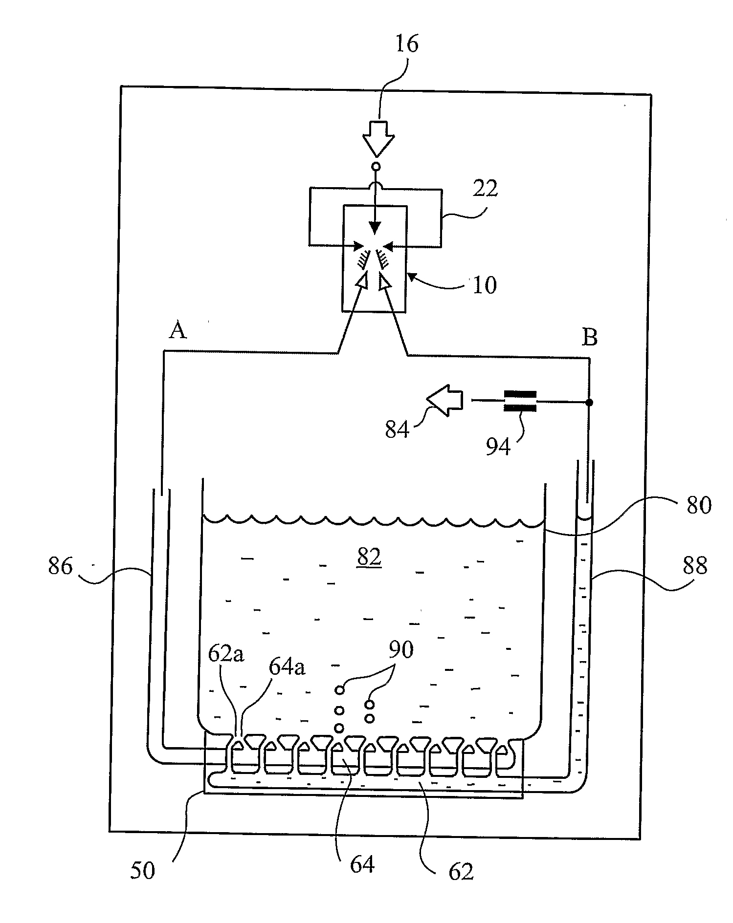
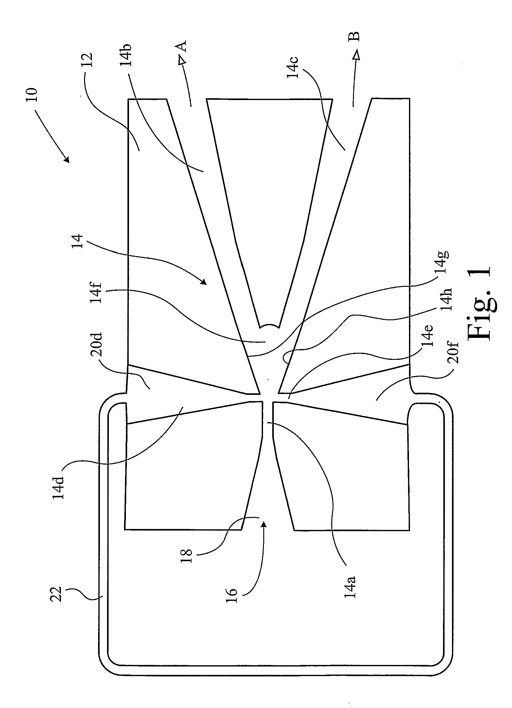
[0066]In FIG. 1 a fluidic diverter 10 is shown in section, comprising a block 12 in which passages indicated generally at 14 are formed. An inlet passage 14a has a supply 16 of fluid under pressure connected thereto by an inlet port 18. Two outlet passages 14b,c branch from the inlet passage 14a. Two control passages 14d,e oppose one another on either side of the inlet passage just in front of the branch 14f between the two outlet passages 14b,c. The control passages are supplied by control ports 20d,f which are interconnected by a closed loop conduit 22. When fluid passes along the inlet passage 14a and enters the diverging branch 14f it tends to cling to one side or the other under the influence of the Coanda effect, and preferentially enters one or other of the outlet passages 14b,c. In fact, the effect is so strong that, provided the pressure region upstream of the outlet passages 14b,c is favourable, more than 90% of flow in the inlet passage 14a will enter one or other of the ...


PUM

PropertyMeasurementUnit
Fractionaaaaaaaaaa
Fractionaaaaaaaaaa
Diameteraaaaaaaaaa

Abstract

A method of producing small bubbles (90) of gas in a liquid comprises a source (16) of the gas under pressure, a conduit (64a) opening into a liquid and oscillating the gas passing along the conduit at a frequency between 1 and 100 Hz. The oscillation is effected by fluidic oscillator (10) comprising a diverter that divides the supply into respect outputs (A, B), each output being controlled by a control port, wherein the control ports are interconnected by a closed loop (22). There may be at least two of said conduits (62a, 64a), each output port being connected to one or the other of said conduits, in which one phase of the oscillating gas is employed to drive liquid across the conduit (64a) after formation of a bubble in the other phase of oscillation, whereby the bubble is detached by the force of said driven liquid.

Description

[0001]This invention relates to the generation of fine bubbles.BACKGROUND[0002]Bubbles of gas in liquid are frequently required in many different applications and usually, but not exclusively, for the purpose of dissolving the gas in the liquid. Like any industrial process, it is generally desired that this be done in the most efficient manner possible which, in the case of dissolving the gas in the liquid, does not involve the bubble reaching the surface of the liquid and releasing the gas there without it having been dissolved. Ideally, the bubbles should not reach the surface before all the gas in them has dissolved. It is widely recognised that one way to achieve efficiency is to reduce the size of the bubbles. The surface area to volume ratio of a smaller bubble is higher, and dissolution happens much more rapidly. Moreover, the surface tension of a small bubble means that the gas pressure inside the bubble is relatively much higher than in a large bubble, so that the gas disso...

Claims


Application Information

Patent Timeline
IPC IPC(8): B01F3/04B01F13/02B01F15/02B01F33/40B01F23/00
CPCB01F3/04248F15C1/22B01F15/024B01F3/04978B03D1/1493B03D1/245Y10T137/85938B05B1/08B01F23/23121B01F23/238B01F35/71755C02F3/02B01F23/23105F15B21/12B01F23/20B01F35/71
Inventor ZIMMERMAN, WILLIAM BAUER JAYTESAR, VACLAV
Owner PERLEMAX LTD
Why Eureka
Try Eureka