
Compact spa jet with enhanced air effects

a compact, air-entrainment technology, applied in water installations, physical therapy, construction, etc., can solve the problems of not providing sufficient air entrainment to satisfy or provide enhanced visual aspects, the fluid mechanism has traditionally become more difficult, and the end user's muffled sensation is not satisfied, so as to achieve enhanced visual aspects and more water flow rate

Active Publication Date: 2014-10-28
DLHBOWLES INC
View PDF8 Cites 15 Cited by
  • Summary
  • Abstract
  • Description
  • Claims
  • Application Information

AI Technical Summary

Benefits of technology

The present invention is an improvement over previous fluidic spa nozzles in terms of air entrainment and stability of oscillation. The nozzle has a large aspect ratio and a dual air entrainment mechanism downstream of the throat, which allows for more air entrainment and improved massage performance. The high aspect ratio is necessary to achieve the preferred flow rate of the jet, but it can cause instability in the fluidic oscillator. The invention solves this problem by using a high aspect ratio that also allows for the separation of the layers of the stream or jet, which reduces the loss of cohesiveness and the resulting massage effect.

Problems solved by technology

However, the resulting fluid mechanism have traditionally become more challenging, likely due to the formation of cross-flow patterns in the depth direction.
In the early development stage, the nozzle had a 7 degree taper angle; its oscillation was erratic or the output jet rolled, which resulted in a muffled sensation to the end user.
The dual air entrainment mechanism was developed to overcome previous mechanisms which did not provide sufficient air entrainment to satisfy or provide enhanced visual aspects.
High aspect ratio jets have a tendency to produce unstable fluidic oscillators, where the cohesiveness of the stream or jet is lost.
The end result of this out-of-phase condition is that the massage effect is lost.
The feel is so intuited that the user cannot determine the oscillation of the jet.
The relatively small contact patch on the user's body, due to proximity of the body to the jet, accentuates this problem.
Additionally, the tight packaging space required special manufacturing and assembly methods to be employed.

Method used


Image

  • Compact spa jet with enhanced air effects
  • Compact spa jet with enhanced air effects
  • Compact spa jet with enhanced air effects

Examples


Embodiment Construction

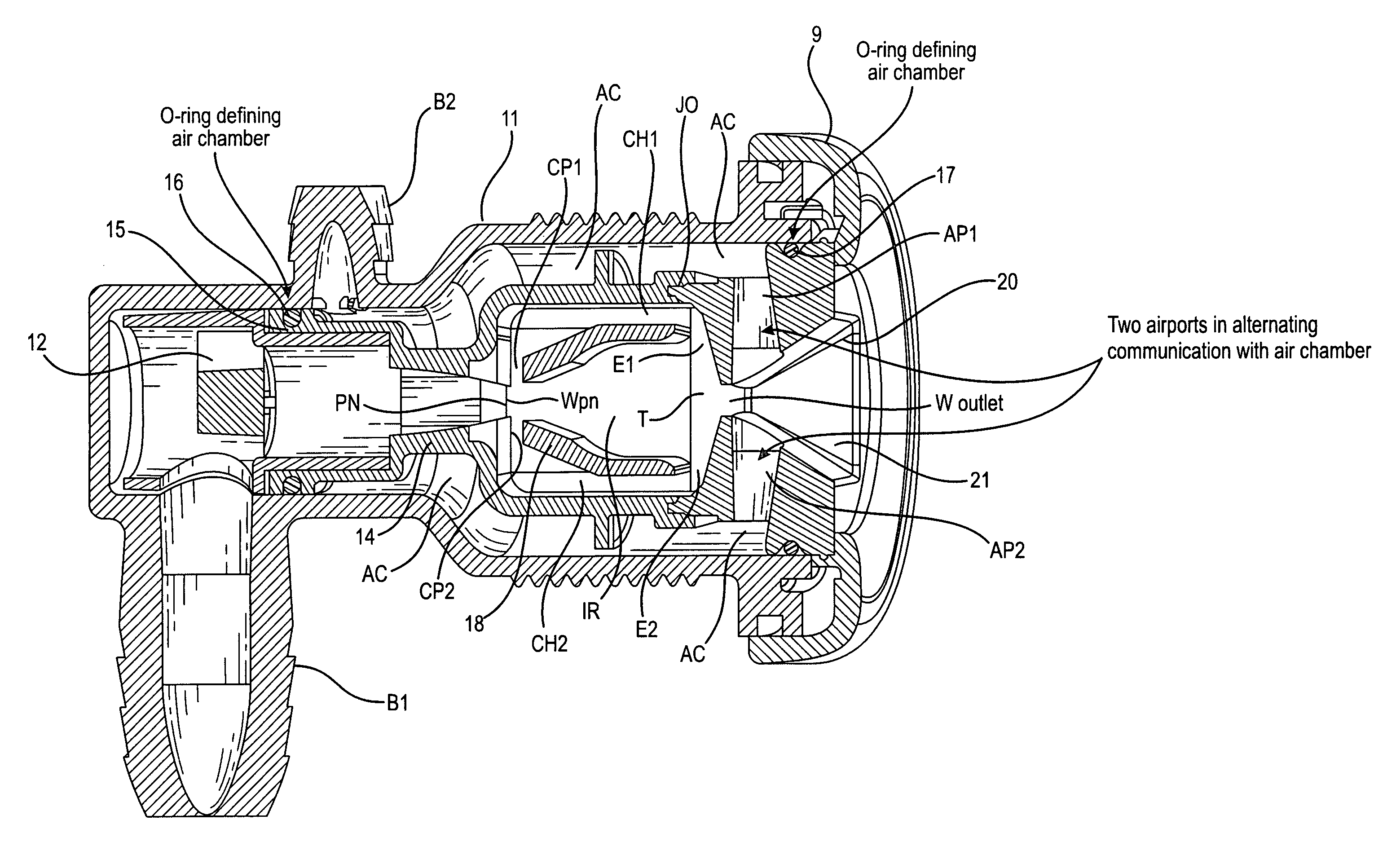
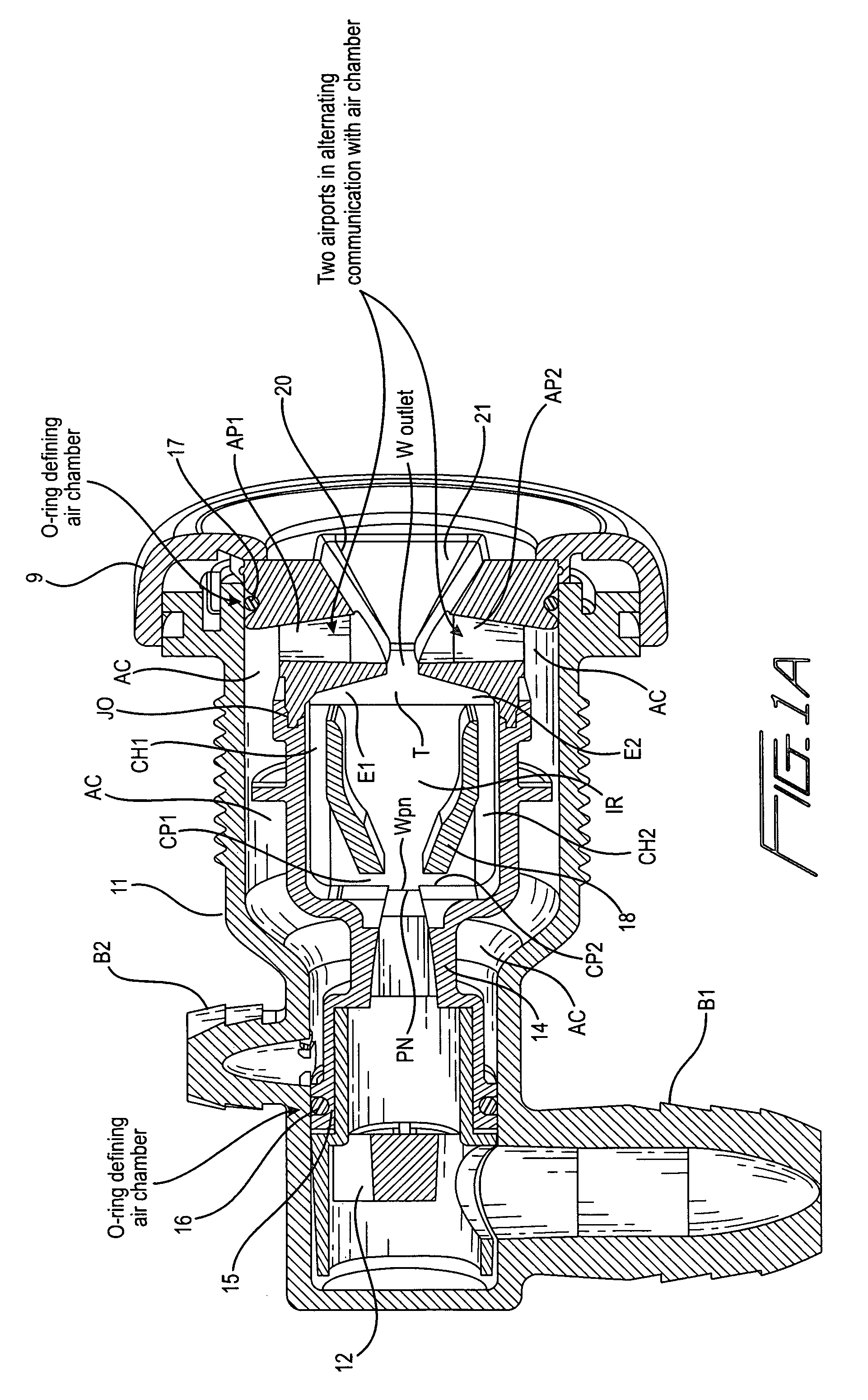
[0023]As shown in the drawings, a molded, threaded housing H has a water input barb B1 and an air input barb B2 coupled respectively to water and air supplies (not shown). The water input barb B1 feeds a conventional flow straightener 12 which feeds water to a power nozzle PN in the fluidic oscillator. A molded fluidic housing 14 has a seat 15 for an O-ring 16 which in conjunction with O-ring 17 forms an air chamber AC (FIG. 1A) coupled to air barb B2. Fluidic insert 18 incorporates the power nozzle PN and the interaction regional IR. Feedback channels CH1 and CH2 are formed between the walls of the fluidic housing and the insert 18. After the fluidic insert 18 is inserted in fluidic housing 14, the fluidic outlet FO is attached by welding (sonic, RF, etc.) or adhesive at joint JO. Outlet OB is secured or attached to the fluidic outlet FO in a similar fashion. The air chamber formed between the two O-rings 16 and 17 is coupled to a pair of air ports AP1 and AP2, respectively, which ...


PUM


Abstract

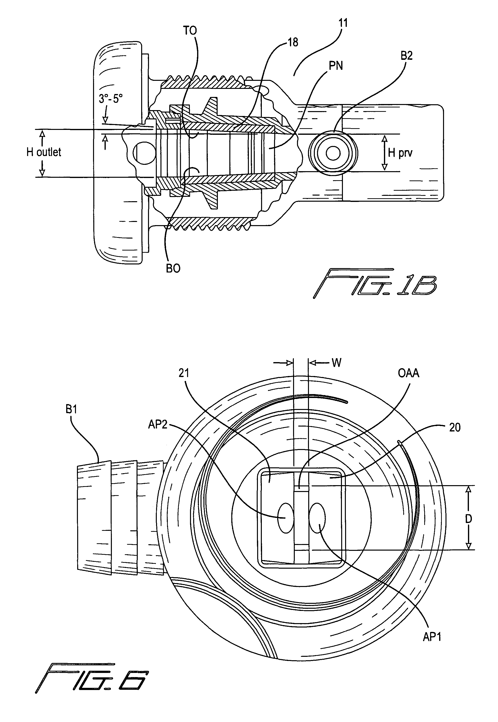
A spa nozzle has a fluidic oscillator for oscillating a jet of water back and forth through an outlet aperture and a pair of diverging sidewalls extending downstream of the outlet aperture for issuing a sweeping jet of water into the spa. An air entrainment port is formed in each diverging sidewall downstream of the outlet aperture. The top and bottom walls in the oscillator interaction region diverge sufficiently so as to provide a relatively large outlet aperture area but not so large as to cause the jet to roll as it exits the outlet aperture, and wherein the ratio of the depth D of the power nozzle to the width W thereof is from about 2.9 to about 3.1 and the ratio of the depth D of the outlet throat to the width W thereof is from about 4.4 to about 4.6.

Description

REFERENCE TO RELATED APPLICATION[0001]The present invention claims the benefit of and priority of provisional application No. 60 / 849,009 filed Oct. 4, 2006.BACKGROUND AND BRIEF DESCRIPTION OF THE INVENTION[0002]Thurber, Jr. et al U.S. Pat. No. 6,575,386, entitled SPA NOZZLE WITH AIR ENTRAINMENT, issued Jun. 10, 2003, to the assignee hereof discloses a spa nozzle in which a jet of water passes over an air entrainment port downstream of the outlet. The present invention is an improvement over the Thurber, Jr. et al patent in that it relates to a small package size, oscillating fluidic for use in spa and bath products.[0003]Increasing jet count and configurability of individual seats in hot tubs / spas and bath products are driving down the packaging envelope allowed for massage jets. These small packages are still required to have the same functionality as their larger brothers in terms of mechanical performance like shutoffs and massage performance, two key characteristics being water ...

Claims


Application Information

Patent Timeline
Patent Type & Authority Patents(United States)
IPC IPC(8): A61H33/02A61H33/04
CPCA61H33/027A61H33/6057B05B1/08
Inventor SANTAMARINA, ALANDROMACK, ALAN
Owner DLHBOWLES INC
Learn More