System and method for reducing skew in complementary signals that can be used to synchronously clock a double data rate output

a complementary signal and clocking signal technology, applied in the field of electronic circuitry, can solve the problems of clock skew, delay of one clock relative, and jitter of one complementary pair, so as to minimize clock skew, jitter, and noise placed on complementary signals.

Active Publication Date: 2006-11-14
MONTEREY RES LLC
View PDF9 Cites 28 Cited by
  • Summary
  • Abstract
  • Description
  • Claims
  • Application Information

AI Technical Summary

Benefits of technology

The problem addressed by this patent is how to reduce issues like clock skew, jitter, and noise when placing complementary signals (such as clock signals) into electronic systems. By adjusting these signals regularly, they create better quality outputs with minimal delays between transition times. This results in an improvement in overall performance for the system.

Problems solved by technology

This patent discusses how electronic devices use clock signals to ensure they function properly. However, sometimes these signals can become distorted which causes delays in the device's operation. The technical problem addressed in this patent is reducing clock skew (the variation in cycle times) and jitter (unpredictable variations in signal quality) in complementary clock signals used in electronic devices to improve their overall performance and consistency.

Method used


Image

  • System and method for reducing skew in complementary signals that can be used to synchronously clock a double data rate output
  • System and method for reducing skew in complementary signals that can be used to synchronously clock a double data rate output
  • System and method for reducing skew in complementary signals that can be used to synchronously clock a double data rate output

Examples


Embodiment Construction

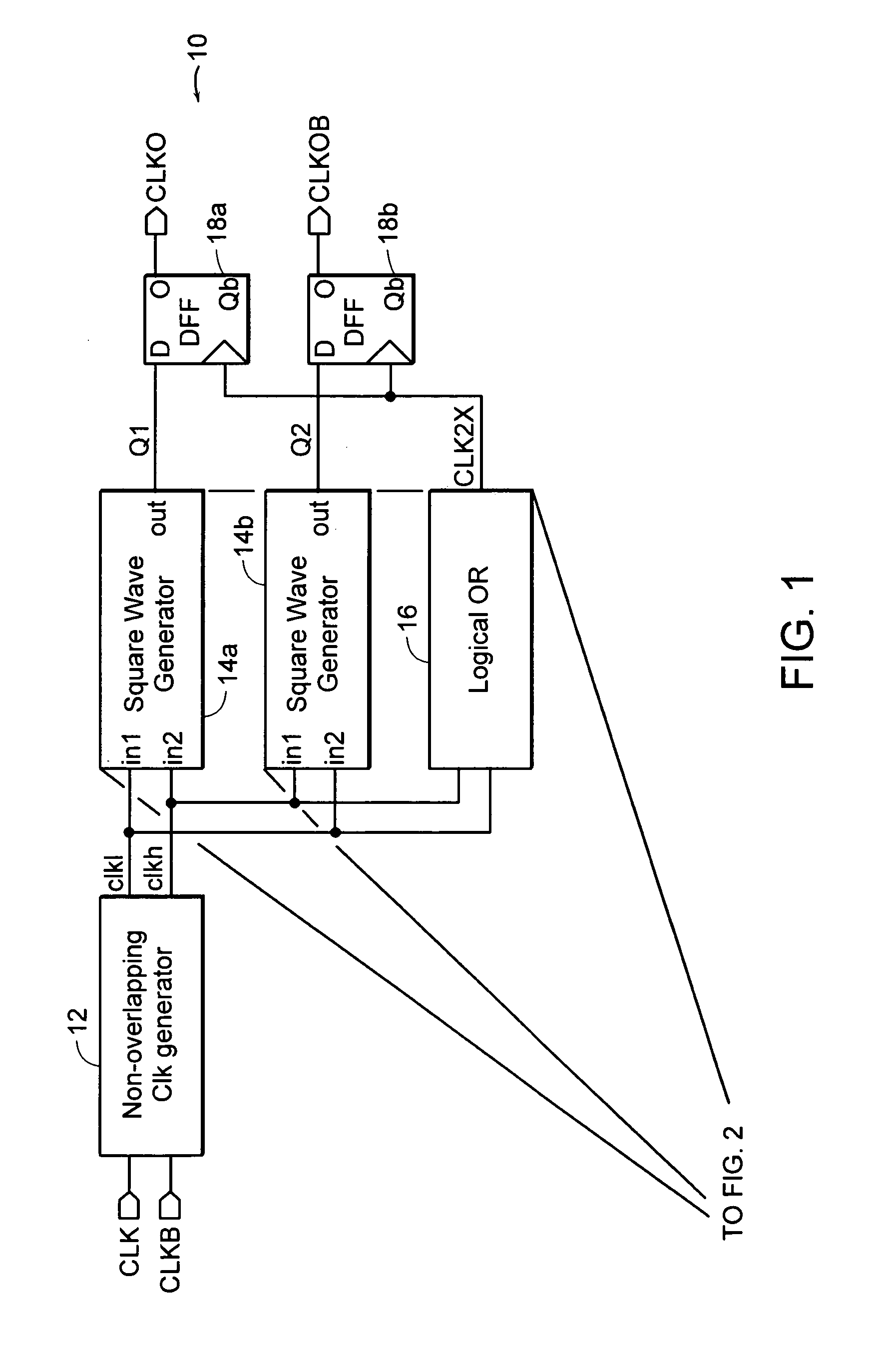
[0027]Turning now to the drawings, FIG. 1 is a block diagram of a circuit 10 used for generating complementary output signals that have little if any skew. Circuit 10 includes a clock generator 12 that generally operates as a mono-stable multi-vibrator, oftentimes referred to as a “one-shot.” One-shot 12 has only one stable state and a quasi-stable state. During operation, the one-shot remains in its stable state until a triggering signal is received, such as a rising edge on the true input clock signal (CLK) or the rising edge of the inverted input clock signal (CLKB). Upon receipt of the rising edges, the one-shot changes to the quasi-stable state for a fixed period of time. That time value is predetermined based on the cycle length of the true and inverted complementary pair of input signals. It is generally desired that the fixed period of time be somewhere less than ¼ cycle of the complementary pair of input signals, both of which transition at the same rate.

[0028]Circuit 10 al...


PUM


Abstract

A circuit, system, and method are provided for generating edge-aligned, complementary output signals from complementary input signals. The output and input signals can, according to one example, be clock signals. The circuit, system, and method can use the rising edges of the complementary pair of input signals to trigger transitions on the complementary pair of output signals. More specifically, the rising edge of a true input clock signal will trigger the rising edge of the true output clock signal and the falling edge of the inverted output clock signal. A rising edge of the inverted input clock signal will trigger the falling edge of the true output clock signal, and the rising edge of the inverted output clock signal. Moreover, the circuit, system, and method ensures that at any time only one transition occurs on the active inputs of a final logic stage of the clock generation circuit. Also, the circuit, system, and method support double data rate (DDR) data and echo clock generation, where the echo clock transitions in sync with the DDR output.

Description


Claims


Application Information

Patent Timeline
Owner MONTEREY RES LLC
Why Eureka
Try Eureka