
Memory Controller Idle Mode

a memory controller and idle mode technology, applied in the direction of instruments, liquid/fluent solid measurement, generating/distributing signals, etc., can solve the problems of corruption of data during subsequent access of memory, the memory controller may not support dynamic changes in their operation, and the power consumption of the electronic device decreases

Active Publication Date: 2008-07-03
TEXAS INSTR INC
View PDF14 Cites 37 Cited by
  • Summary
  • Abstract
  • Description
  • Claims
  • Application Information

AI Technical Summary

Benefits of technology

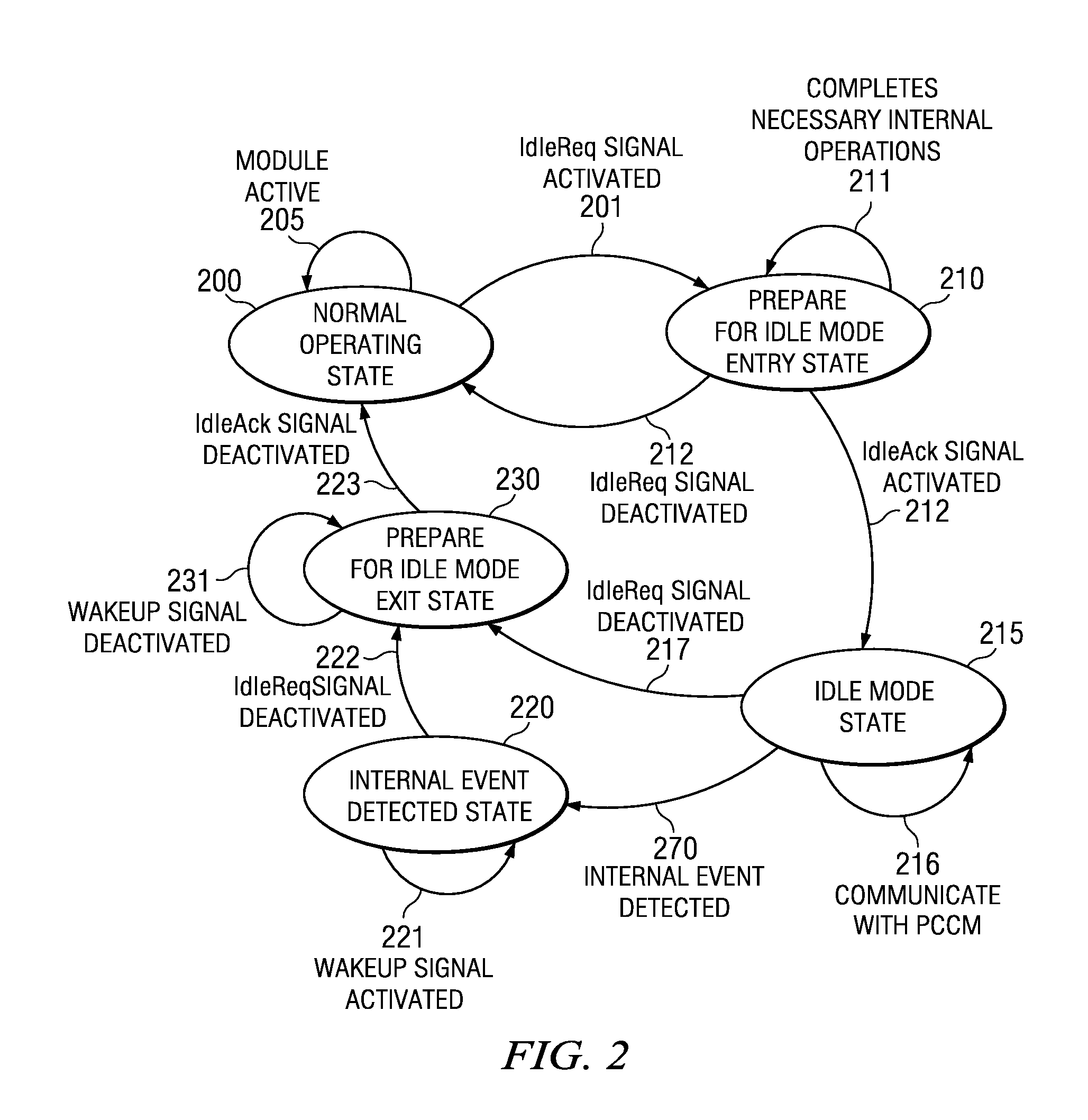
The patent describes a way to change the settings of a memory controller in an electronic device to optimize performance. This can include changing the clock frequency and power, and using an idle mode for the memory controller. The memory controller can have multiple modes of operation that can vary depending on the type of memory it controls. The method includes preparing the memory controller and memory for modification, denying access to the memory controller while the settings are being changed, and reinstating access under the new settings. The patent also describes an electronic device that includes circuitry to dynamically modify the memory controller's settings and the memory controller's response to those changes.

Problems solved by technology

By turning off clock signals that drive inactive circuits, the power consumption of the electronic device decreases.
Some memories and memory controllers may not support dynamic changes in their operation to reduce power consumption using the techniques described above.
If the clock is gated or the frequency is changed, the DLL may unlock, causing corruption of data during a subsequent access of memory.
Further complications to dynamic operating conditions are introduced by complex integrated circuitry.
The latency and difficulty required to prevent all components from accessing the memory controller for each operating condition change may degrade performance, increase software complexity and result in inefficient, operation.
Furthermore, SOC systems including multiprocessors may require additional software synchronization.
Finally, accesses to memory components such as hardware accelerators, camera interfaces, and display interfaces on the SOC may be difficult to stop.
Waiting until each component completes processing increases latency.
This may greatly limit dynamically changing operating conditions to reduce power consumption.

Method used


Image

  • Memory Controller Idle Mode
  • Memory Controller Idle Mode
  • Memory Controller Idle Mode

Examples


Embodiment Construction

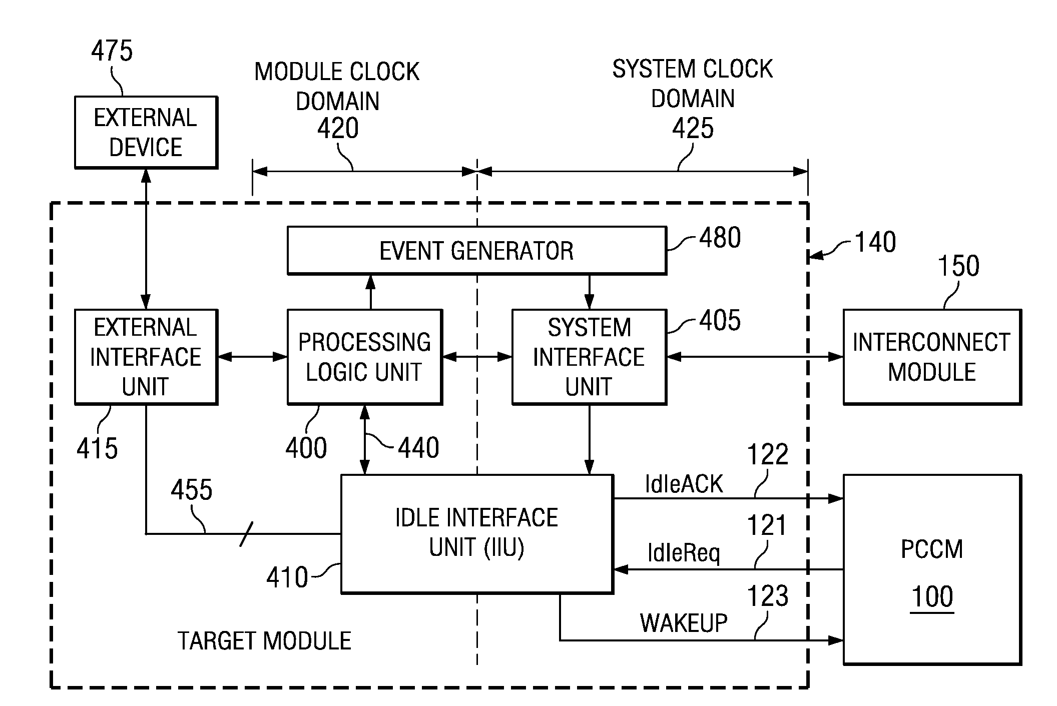
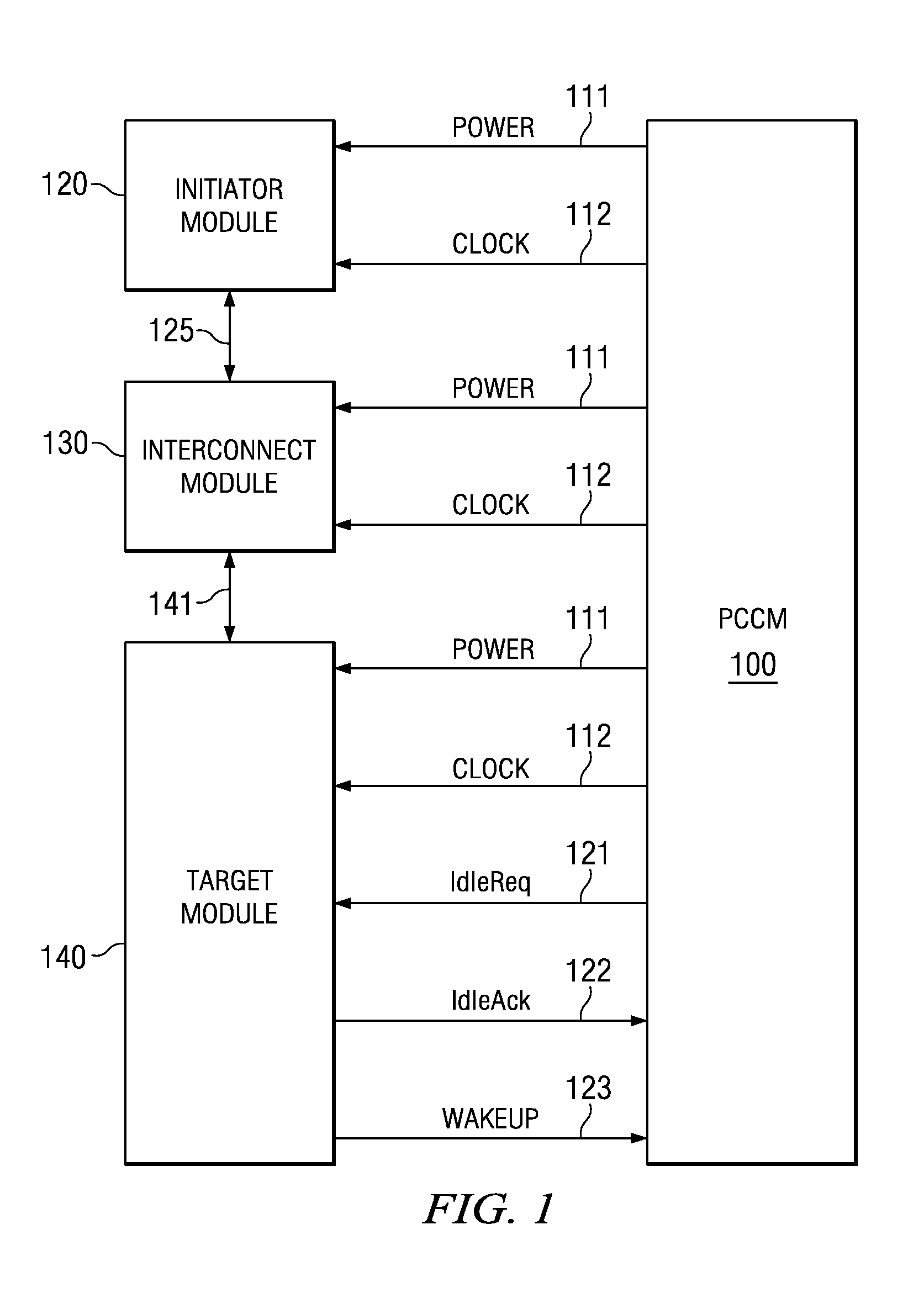
[0018]In accordance with some embodiments of the invention, in an electronic device, a power and clock control module (PCCM) couples to an initiator module, interconnect module, and target module. An initiator module is any logic circuitry that may generate write requests or read requests. Thus, the initiator module may be a processor, graphics accelerator, display controller, audio interface, digital signal processor, microcontroller unit (MCU), direct memory access (DMA) device, video accelerator, universal serial bus (USB) device, or a peripheral device that is capable of initiating read or write requests, and so on. An interconnect module may be any logic circuitry capable of routing information from an initiator module to a target module. Examples of interconnect modules are a bus, an interconnection network, and so on. A target module is any logic circuitry that is the destination of a write request or a read request. Examples of target modules include memory devices such as a...


PUM


Abstract

An apparatus and method for dynamically modifying one or more operating conditions of a memory controller in an electronic device. Operating conditions may comprise clock frequency and power, which may be modified or removed. Dynamic modification of operating conditions may be done for purposes of optimizing a parameter, such as power consumption. A mode, referred to as idle mode, may be used as a transitional or operational mode for the memory controller. The performance of the memory controller may dynamically vary in response to changes in its operating conditions. As such, the memory controller may comprise multiple modes, or submodes, of operation. The performance of the memory controller may depend on the type of memory it controls, for instance Double Data Rate (DDR) Dynamic Random Access Memory (DRAM).

Description

CROSS REFERENCE TO RELATED APPLICATIONS[0001]This application claims priority under 35 USC § 119(e)(1) of Provisional Application No. 60 / 883,032, filed Dec. 31, 2006, incorporated herein by reference.FIELD OF THE INVENTION[0002]The present invention generally relates to dynamic operating conditions in an electronic device. More particularly, the invention relates to a transitional mode or operational mode for dynamic transitions in the functioning of the electronic device.BACKGROUND OF THE INVENTION[0003]Dynamic operating conditions are commonly used to improve performance of electronic devices, including their power consumption. Reducing power consumption in electronic devices is desirable for many reasons. Reducing consumption of power lowers the heat generated by the device, thereby increasing the reliability and decreasing the operating cost of the device. In addition, reducing the consumption of power allows battery-powered portable electronic devices, such as cellular telephon...

Claims


Application Information

Patent Timeline
Patent Type & Authority Applications(United States)
IPC IPC(8): G06F5/06G06F12/00
CPCY02B60/1228G06F13/1694Y02D10/00
Inventor DAHAN, FRANCKDUBOST, GILLESDUBOIS, SYLVAIN
Owner TEXAS INSTR INC
Learn More