Microscope with a handle and/or hand-grip for a microscope

a technology of microscope and handle, which is applied in the direction of surgical microscopes, mechanical control devices, instruments, etc., can solve the problems of increasing space being used, and space problems for assistants, so as to improve the overall weight of the microscope structure, reduce weight, and improve the effect of grip arrangement or configuration

Inactive Publication Date: 2006-11-14
LEICA INSTR SINGAPORE PTE
View PDF17 Cites 8 Cited by
  • Summary
  • Abstract
  • Description
  • Claims
  • Application Information

AI Technical Summary

Benefits of technology

[0007]This object is achieved by means seen in the present specification. The replacement of two hand-grips by one hand-grip which is fitted, or can be detachably fitted, at a central point of the microscope body and extends in at least two space directions of the coordinate system, leads firstly to a substantial weight reduction, and secondly to the possibility of operating the microscope with only one hand. The space problems mentioned for the assistants are thereby eliminated. The extension in at least two space directions provides the user with the option of applying various pivoting movements with only one hand and applying favourable leverages in the process.The single-handed operation according to the invention by means of a single hand-grip makes it easier for the user to vary the position of the microscope while simultaneously using the other hand for other activities.A second object on which the invention is based is thus to improve this problem. This object is achieved by creating a hand-grip which can be detached from the microscope body. Since the ergonomy and the speed during detachment are to be kept generous, it is preferred according to the invention to provide single-handed operation.

Problems solved by technology

However, this disadvantageously results in space being used by the hand-grips which would otherwise be free.
Chiefly, in the case of built-on accessories with assistant terminals, this leads to space problems for assistants.
Above all, the hand-grips fastened on rods disadvantageously increase the overall weight of the microscope structure which must be borne by the stand.

Method used


Image

  • Microscope with a handle and/or hand-grip for a microscope
  • Microscope with a handle and/or hand-grip for a microscope
  • Microscope with a handle and/or hand-grip for a microscope

Examples


Embodiment Construction

[0019]Identical components bear the same reference numerals in the following description of the figures, while different components bear different reference numerals.

Different components having the same functions bear the same reference numerals with different indices.

The figures are described as a whole.

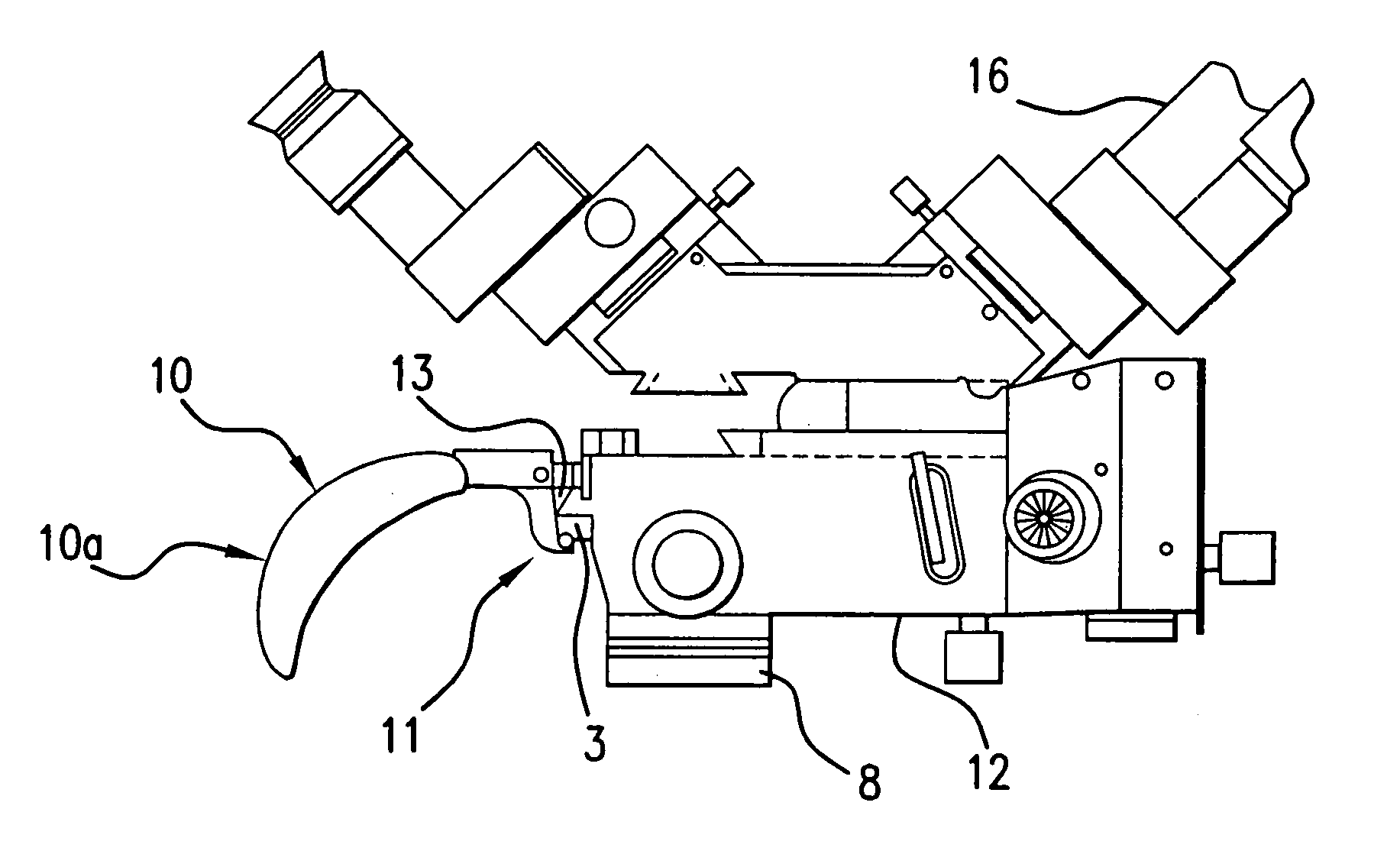
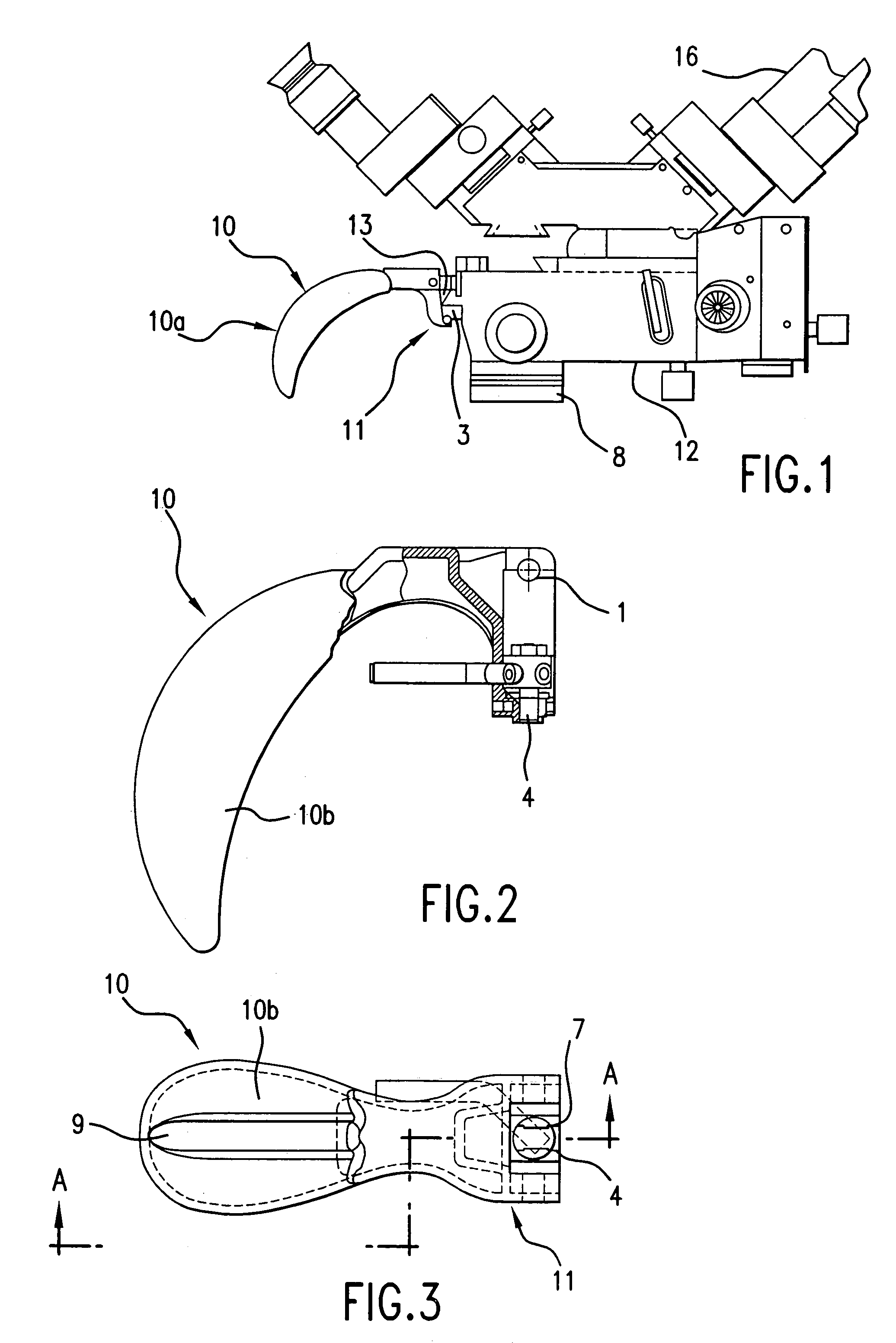
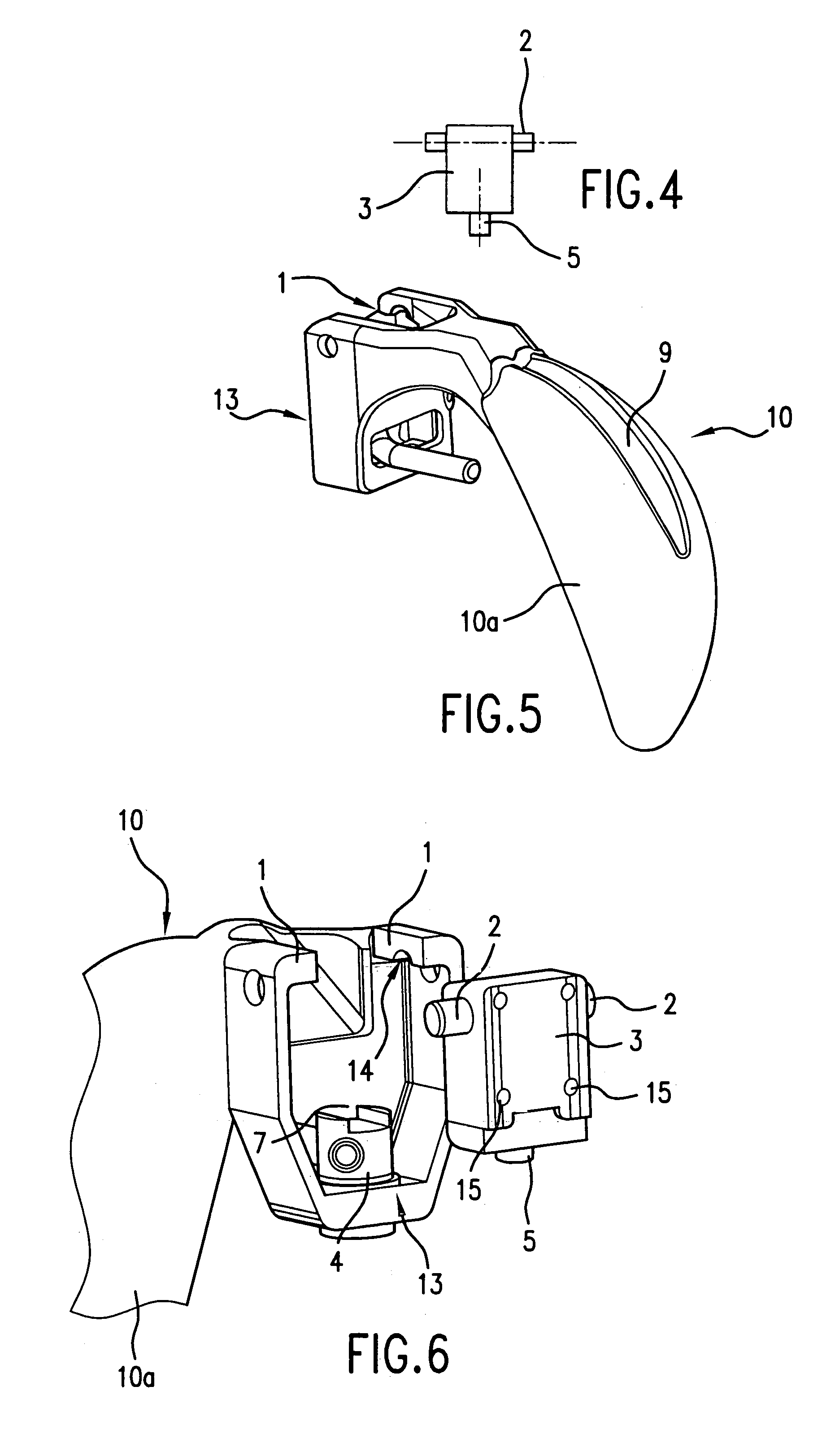
A microscope body 12 with a main objective 8 has at a central point a holding piece 3 which is constructed on the microscope body 12 or is permanently connected to the latter, for example by screws in fastening bores 15 (FIG. 6).

[0020]The holding piece 3 serves to a hold a mounting part 11 with the gripping part 10 of the novel hand-grip. A plurality of such holding pieces could be mounted on the microscope body or on the pivoted support 16 or on the stand or at other locations. The holding piece 3 has two bearing pins or a shaft 2 at the upper end of the holding piece 3, and a thrust bolt 5 at the lower end of the holding piece 3.

Both the shaft 2 and thrust bolt 5 and, if appropria...


PUM


Abstract

The invention relates to a hand-grip with a grip part which can be detachably fastened on a microscope housing, the mounting and dismounting being possible with a single-handed movement with the gripping hand. The hand-grip is fashioned and positioned such that it permits operation of the microscope in all directions with only one hand.

Description

CROSS REFERENCE TO RELATED APPLICATIONS[0001]This invention claims priority of the Swiss patent application 1897 / 00 which is incorporated by reference herein.FIELD OF THE INVENTION[0002]The invention relates to the hand-grip on a microscope—from the type of fastening on the microscope housing, on the one hand, and from the number of fastening locations and the location of fastening on the microscope, on the other hand.[0003]In particular, the invention relates to a hand-grip for a microscope which can be fitted in an ergonomic and comfortable way on a microscope which is suspended on a suitable moving stand such that the microscope can also be moved under sterile conditions in space. Such movements include up / down, forward / back, sideways, rotate, pivot, incline, etc.BACKGROUND OF THE INVENTION[0004]Conventional hand-grips have become known in the most varied forms and mounting types. They are mostly screw in pairs (left and right) on the microscope housing, or constructed on rods wh...

Claims


Application Information

Patent Timeline
Patent Type & Authority Patents(United States)
IPC IPC(8): G02B21/10F16M11/04G05G1/12A47J45/00F16K35/02G02B7/00G02B21/00G02B21/24G05G1/00G05G1/04
CPCG02B7/001G02B21/24G02B21/0012A61B19/5223Y10T74/20642A61B90/20
Inventor STROBEL, PETERSOLLBERGER, FRITZ
Owner LEICA INSTR SINGAPORE PTE
Why Eureka
Try Eureka