Circuit for compensating a degraded signal and associated method

Active Publication Date: 2006-11-14
VIA TECH INC
View PDF6 Cites 6 Cited by
  • Summary
  • Abstract
  • Description
  • Claims
  • Application Information

AI Technical Summary

Benefits of technology

[0015]It is an advantage that the claimed invention uses a dynamic detection and compensation method to adjust the signal levels so as to correct the deviations of the signal levels c

Problems solved by technology

Several problems can occur during the signal transmission process.
However, a high pass characteristic of the transformer in the signal circuit undesirably affects the signal level of the transmission signal.
The Ethernet network system suffers from this high pass problem.
The baseline w

Method used


Image

  • Circuit for compensating a degraded signal and associated method
  • Circuit for compensating a degraded signal and associated method
  • Circuit for compensating a degraded signal and associated method

Examples


Embodiment Construction

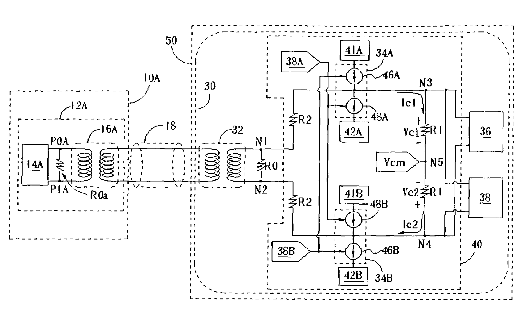
[0021]Please refer to FIG. 3, which is a schematic diagram of a signal circuit 30 used in a network system according to the present invention. A user terminal 10A and a user terminal 50 are connected with each other via a network transmission line 18. The user terminals 10A and 50 can be network servers, routers, clients, or other network terminals. The transmission line 18 can be an Ethernet Unshielded Twisted Pair Category 5 (UTP-Cat.5) cable, and a transmission signal can be an MLT-3 coded, or 100Base-T coded signal. The user terminal 10A and the user terminal 50 use a signal circuit 12A and a signal circuit 30 respectively to process transmission signals. The signal circuit 12A includes a transformer 16A and a resistor R0a that is matched to the impedance of the transformer 16A. The signal circuit 30 includes a transformer 32 and a resistor R0 that is matched to the impedance of the transformer 32. A transmitter 14A of the signal circuit 12A generates a transmission signal. A re...


PUM


Abstract

A signal compensation circuit and associated method dynamically compensate for signal baseline wandering in a transmission line. The compensation circuit has a detection circuit and a correction circuit. The detection circuit first compares a transmission signal with a reference level and generates a comparison result. The correction circuit then corrects the transmission signal according to the comparison result. The compensation circuit can adjust its compensation over time based on the quality of the transmission signal.

Description

BACKGROUND OF INVENTION[0001]1. Field of the Invention[0002]The present invention relates to a circuit for receiving a transmission signal and associated method, and more particularly, to a circuit for dynamically compensating a baseline wander of the transmission signal and associated method.[0003]2. Description of the Prior Art[0004]Please refer to FIG. 1, which is a schematic diagram of typical user terminals 10A and 10B connected to each other by a network transmission line 18. The user terminals 10A and 10B can be network servers, routers, clients, or other kinds of network terminals. The transmission line 18 is a network transmission line, such as an Unshielded Twisted Pair Category 5 (UTP-Cat.5) Ethernet cable. The user terminal 10A and the user terminal 10B utilize a signal circuit 12A and a signal circuit 12B respectively to transmit signals via the transmission line 18. The signal circuits 12A, 12B include transformers 16A, 16B and resistors R0a, R0b respectively that matc...

Claims


Application Information

Patent Timeline
IPC IPC(8): H04B3/00H04B1/00
CPCH04L25/0266
Inventor LIN, JYH-FONGHSIAO, CHU-YUCHANG, CHIN-CHIWU, MING-YU
Owner VIA TECH INC
Why Eureka
Try Eureka