Variable turbine geometry turbocharger

a turbine geometry and turbocharger technology, applied in the field of turbochargers, can solve the problems of high cost of parts and labor in the assembly of such systems, increased maintenance costs, and high cost of assembling

Active Publication Date: 2006-11-21
BORGWARNER INC
View PDF4 Cites 25 Cited by
  • Summary
  • Abstract
  • Description
  • Claims
  • Application Information

AI Technical Summary

Benefits of technology

[0021]A further advantage of the present invention is that hysteresis assists in the closing of the vanes, because of a pressure reversal that may take place due to the flow around the vanes as they are pivoted from the open position to the closed position.
[0022]The invention tends to eliminate binding of the variable geometry system and maintains the actuator ring and static ring concentrically aligned during operation.

Problems solved by technology

First, the market demands that all components of the power plant of either a passenger car or truck, including the turbocharger, must provide reliable operation for a much longer period than was demanded in the past.
Other considerations include the cost of manufacture of parts and the labor involved in assembly of such systems.
However, the above mentioned design of Engels, for example, contains numerous moving parts that must not only be fabricated individually, but that are also costly to assemble, require more maintenance, and have higher failure rates than are desired.
In addition, friction wear can be a problem with such a design.
These forces result in a cantilevered load on the vanes which introduce stress in the vanes and the various posts.
Over hundreds of thousands of turbocharger cycles, the vanes ultimately become torqued due to the cantilevered loads and hystereis.
Over time, the vanes will become begin to deform and stick and ultimately break or lock.

Method used


Image

  • Variable turbine geometry turbocharger
  • Variable turbine geometry turbocharger
  • Variable turbine geometry turbocharger

Examples


Embodiment Construction

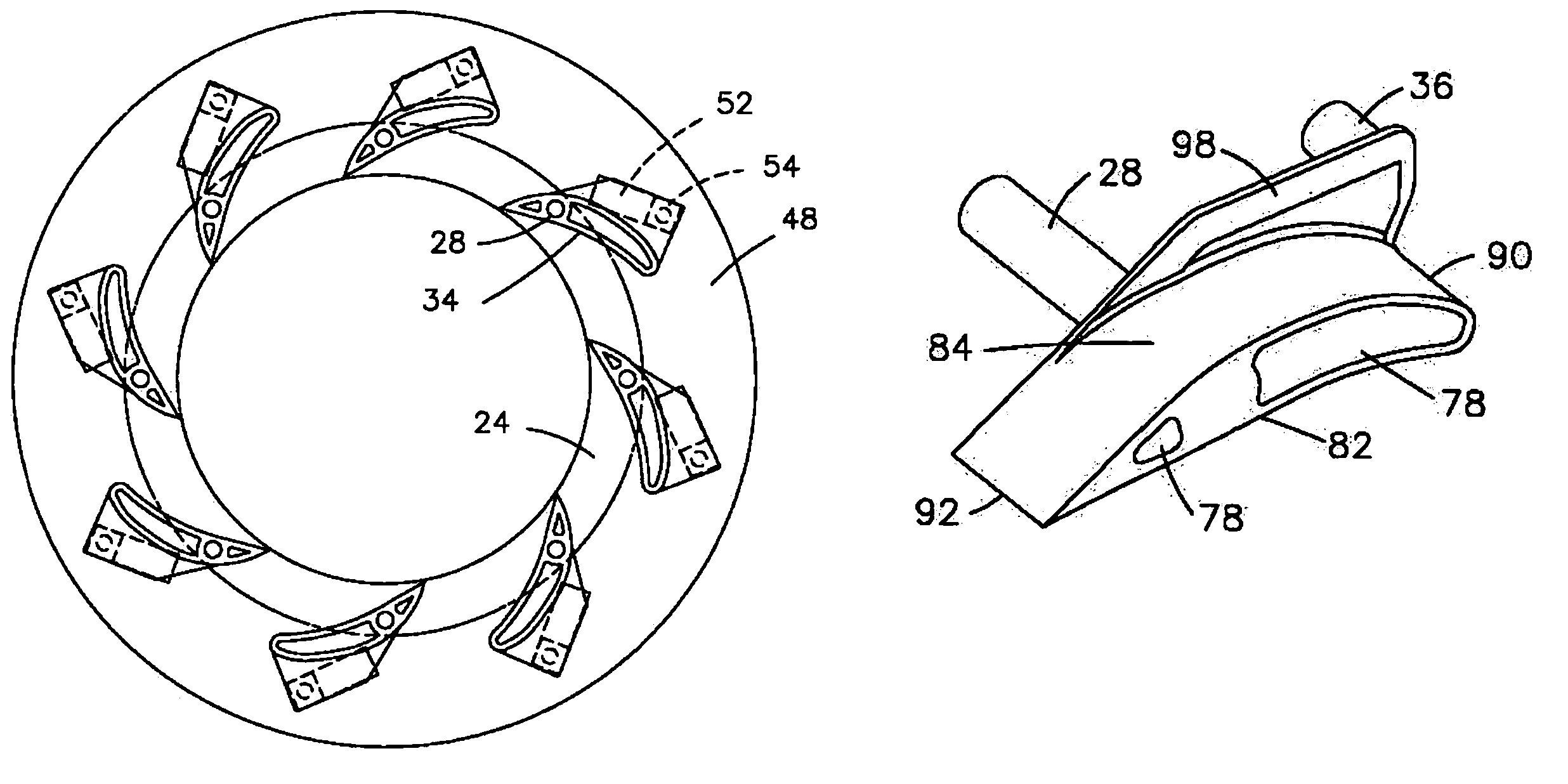
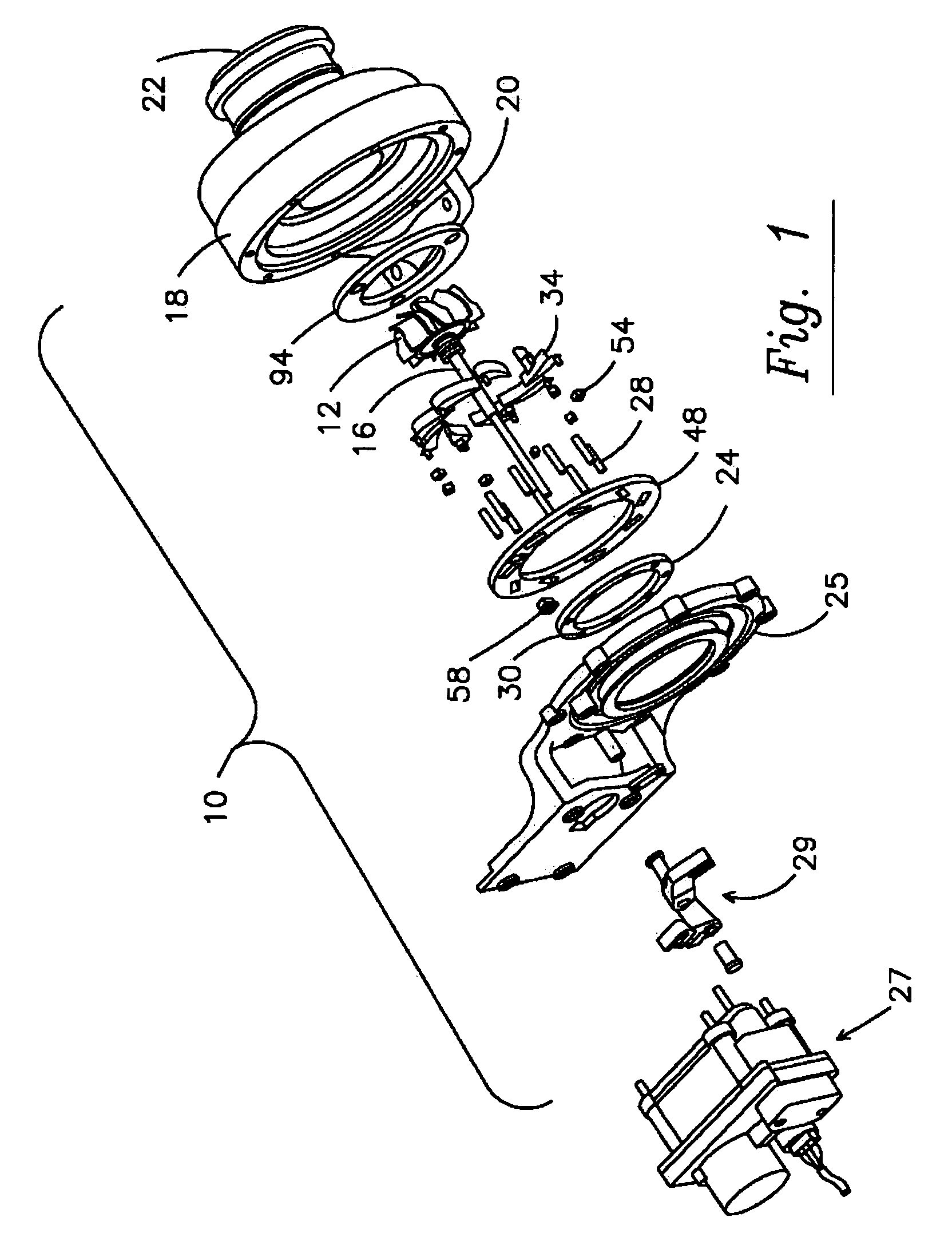
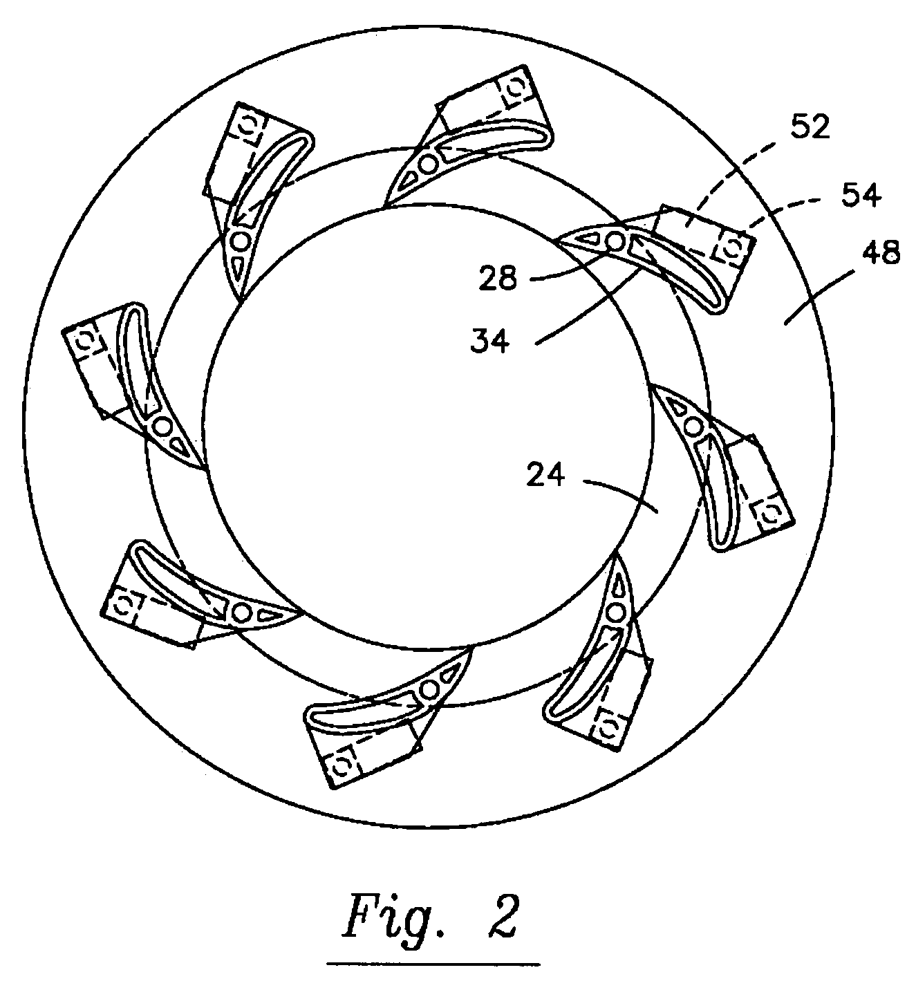
[0030]A turbocharger system as shown in FIG. 1 includes turbomachinery in the form of a turbocharger 10 generally comprising a turbine wheel 12 and a compressor impeller (not shown) mounted on opposite ends of a common shaft 16. The turbine wheel 12 may be disposed within a turbine housing 18 that includes an inlet 20 for receiving exhaust gas from an engine and an outlet 22 for discharging the exhaust gas. The turbine housing 18 guides the engine exhaust gas into communication with and expansion through the turbine wheel 12 for rotatably driving the turbine wheel 12. Such driving of the turbine wheel 12 simultaneously and rotatably drives the compressor impeller that may be carried within a compressor housing (not shown).

[0031]FIG. 1 shows a variable turbine geometry turbocharger with the turbine housing 18 having an exhaust gas inlet 20 and an outlet 22, a volute connected to the inlet 20, and a nozzle wall adjacent the volute (collectively referred to as the exhaust gas supply ch...


PUM


Abstract

A turbocharger arrangement for a variable geometry turbocharger including pivotable vanes (34) with each vane (34) having a respective vane bore (38) for receiving a vane post (28) into a vane first planar surface (80) and a respective actuation post (36) projecting outwardly from the first planar surface (80).

Description

TECHNICAL FIELD[0001]The present invention relates to turbomachinery and more particularly to an improved turbocharger with an improved vane and post arrangement in which the vanes of a variable geometry turbocharger may be pivoted. The pivotable vanes each have a respective vane bore in a planar surface for receiving a vane post and a respective actuation post projecting outwardly from the same planar surface. The mechanism for pivoting the vanes may consist of coplanar rings.BACKGROUND OF THE INVENTION[0002]Turbochargers are widely used on internal combustion engines and, in the past, have been particularly used with large diesel engines, especially for highway trucks and marine applications.[0003]More recently, in addition to use in connection with large diesel engines, turbochargers have become popular for use in connection with smaller, passenger car power plants. The use of a turbocharger in passenger car applications permits selection of a power plant that develops the same a...

Claims


Application Information

Patent Timeline
Patent Type & Authority Patents(United States)
IPC IPC(8): F01D9/04F01D5/14F01D17/16F02C6/12
CPCF01D17/165F02C6/12
Inventor MARCIS, RICHARDHALL, RICHARD
Owner BORGWARNER INC
Why Eureka
Try Eureka