Methods and apparatus for dynamic offset adjustment in a magnetic article detector

a detector and magnetic article technology, applied in the direction of electrical/magnetically converting sensor output, instruments, devices using electric/magnetic means, etc., can solve the problems of relying on the detector output signal, and affecting the detection accuracy of magnetic articles

Active Publication Date: 2006-11-21
ALLEGRO MICROSYSTEMS INC
View PDF6 Cites 62 Cited by
  • Summary
  • Abstract
  • Description
  • Claims
  • Application Information

AI Technical Summary

Benefits of technology

[0013]With this arrangement, the offset-adjusted signal is clamped to a lower level than the fixed offset threshold levels, thereby ensuring that the detector output signal will switch even under conditions of relatively low magnetic field signal magnitude and significant offset shifts.

Problems solved by technology

A variation in the phase of detections of the same feature on different revolutions of the magnetic article or of different features on the same revolution is referred to as an error or jump in the phase of the detector output signal and can disadvantageously affect control units, such as engine control units in automotive applications, relying on the detector output signal.
Detection accuracy is adversely affected if the magnetic field signal experiences a change in magnetic offset.
Changes in the amplitude or offset of the magnetic field signal degrade the accuracy of the magnetic article detection since the magnetic field signal is not centered within the dynamic range of the detector.
In particular, accuracy is degraded when the magnetic field signal shifts so that the PDAC and NDAC signals no longer hold the true magnetic peak / valley.
However, under certain operating conditions, a significantly offset magnetic field signal having a relatively small peak-to-peak voltage may not cross the switching threshold signal, thereby causing a failure of the detector output signal to switch.

Method used


Image

  • Methods and apparatus for dynamic offset adjustment in a magnetic article detector
  • Methods and apparatus for dynamic offset adjustment in a magnetic article detector
  • Methods and apparatus for dynamic offset adjustment in a magnetic article detector

Examples


Embodiment Construction

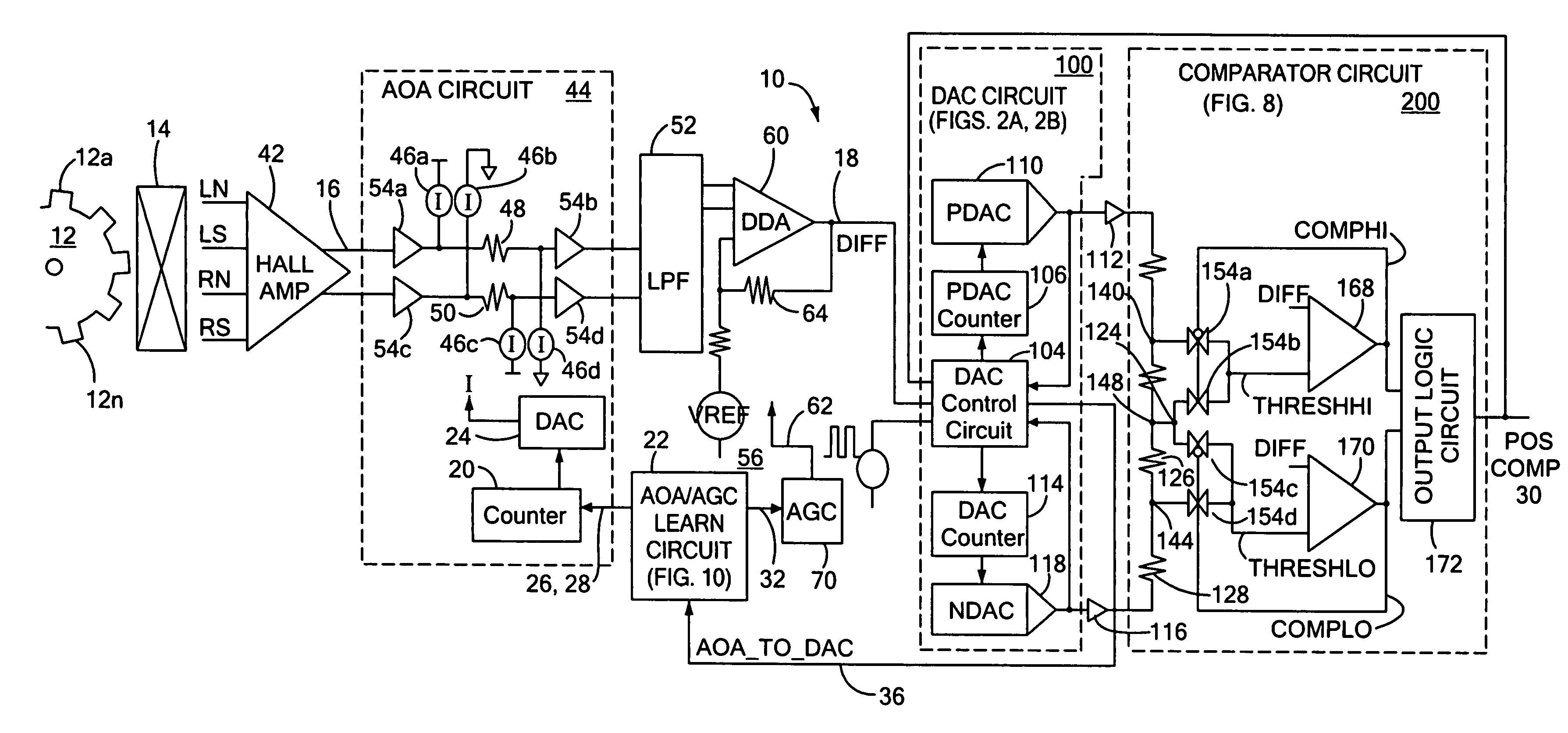
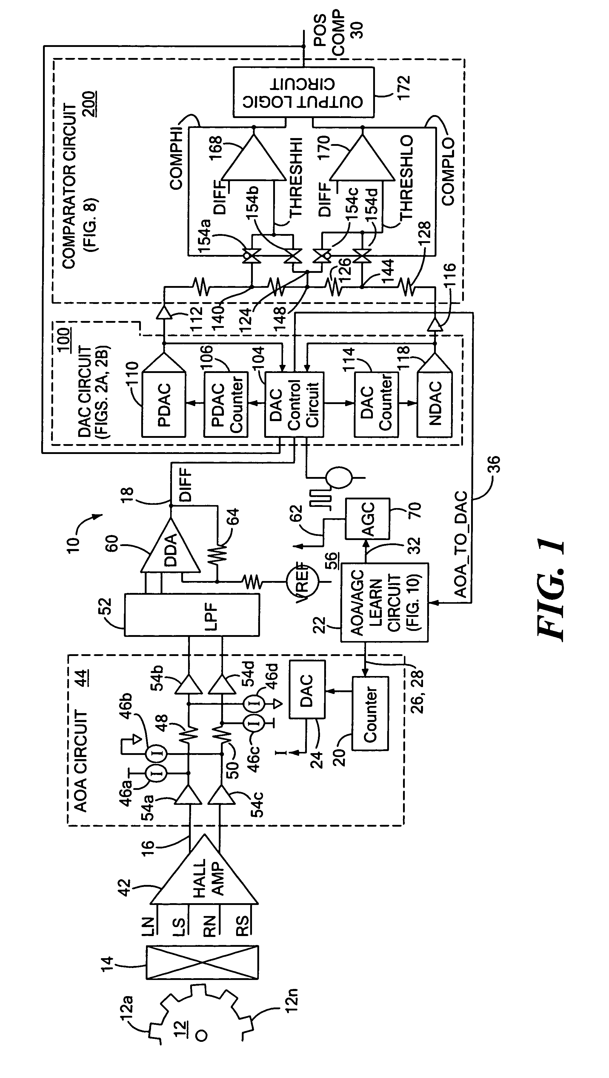
[0028]Referring to FIG. 1, a magnetic article detector 10 includes a magnetic field sensing element 14 providing a signal that is proportional to an ambient magnetic field. The detector 10 is positioned in proximity to a magnetic article, for example a gear 12, so that the output signal of the sensing element 14 is indicative of the profile of the magnetic article 12. The detector 10 provides a detector output signal, POSCOMP, 30 indicative of the magnetic article 12 as it passes through the ambient magnetic field and here, a pulse train having transitions indicating edges of the gear teeth 12a–12n.

[0029]The magnetic field sensing element 14 may take various forms known in the art, including but not limited to a Hall effect element, a vertical Hall effect element, a Giant Magnetoresistive (GMR) element, an Anisotropic Magnetoresistive (AMR) element, and a Tunnel Magnetoresistive (TMR) element. Also, the magnetic field sensing element 14 may comprise a single magnetically responsive...


PUM


Abstract

Apparatus and methods for detecting passing magnetic articles including an offset adjustment circuit for adjusting the DC level of the magnetic field signal based on a dynamically adjustable offset threshold signal. The detector includes a PDAC for tracking the positive peaks of a magnetic field signal and an NDAC for tracking the negative peaks of the magnetic field signal. In one embodiment, the offset threshold signal includes a positive offset threshold signal and a negative offset threshold signal that are initially set at fixed respective signal levels and that become the level of the PDAC signal and NDAC signals, respectively, in response to a counter, that counts a number of increments of the PDAC signal and decrements of the NDAC signal, reaching a predetermined count value.

Description

CROSS REFERENCE TO RELATED APPLICATIONS[0001]Not Applicable.STATEMENT REGARDING FEDERALLY SPONSORED RESEARCH[0002]Not Applicable.FIELD OF THE INVENTION[0003]This invention relates generally to magnetic article detectors and, more particularly, to a magnetic article detector having a dynamic automatic offset adjustment circuit.BACKGROUND OF THE INVENTION[0004]Various types of magnetic field sensing elements or transducers are known, including Hall effect and magnetoresistive elements. Generally, sensors or detectors including magnetic field sensing elements provide an electrical signal representative of the sensed magnetic field and, in the presence of a moving ferromagnetic target object, the magnetic field signal is indicative of the shape or profile of the target object.[0005]Magnetic field sensors are often used to detect gear features, such as gear teeth and / or gear slots. A magnetic field sensor in this application is commonly referred to as a “gear tooth” sensor. Gear tooth se...

Claims


Application Information

Patent Timeline
Patent Type & Authority Patents(United States)
IPC IPC(8): G01B7/14G01P3/42
CPCG01D5/14G01D5/147G01D5/24452G01D5/2448G01D5/2449G01P3/481G01P3/488G01D18/001G01D5/00G01B7/00
Inventor BAILEY, JAMES M.
Owner ALLEGRO MICROSYSTEMS INC
Why Eureka
Try Eureka