
Projection microscope

a microscope and projection technology, applied in the field of microscopes, can solve the problems of little gain for high cost, most improvements, especially to the optical system, and tend to be very expensive, and achieve the effects of high magnification, easy adaptability, and increased magnification

Active Publication Date: 2006-11-21
QUIKMATE
View PDF33 Cites 1 Cited by
  • Summary
  • Abstract
  • Description
  • Claims
  • Application Information

AI Technical Summary

Benefits of technology

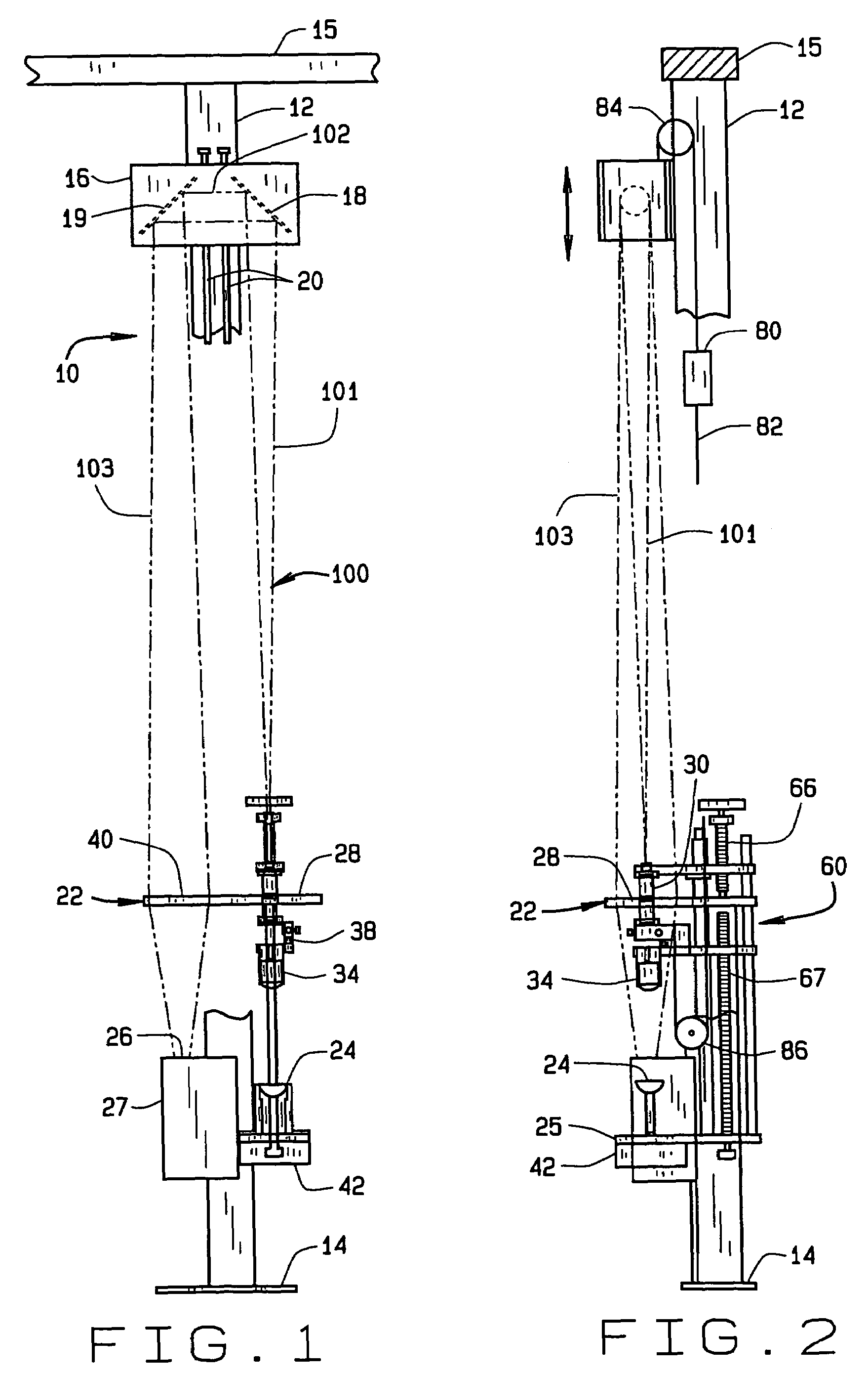
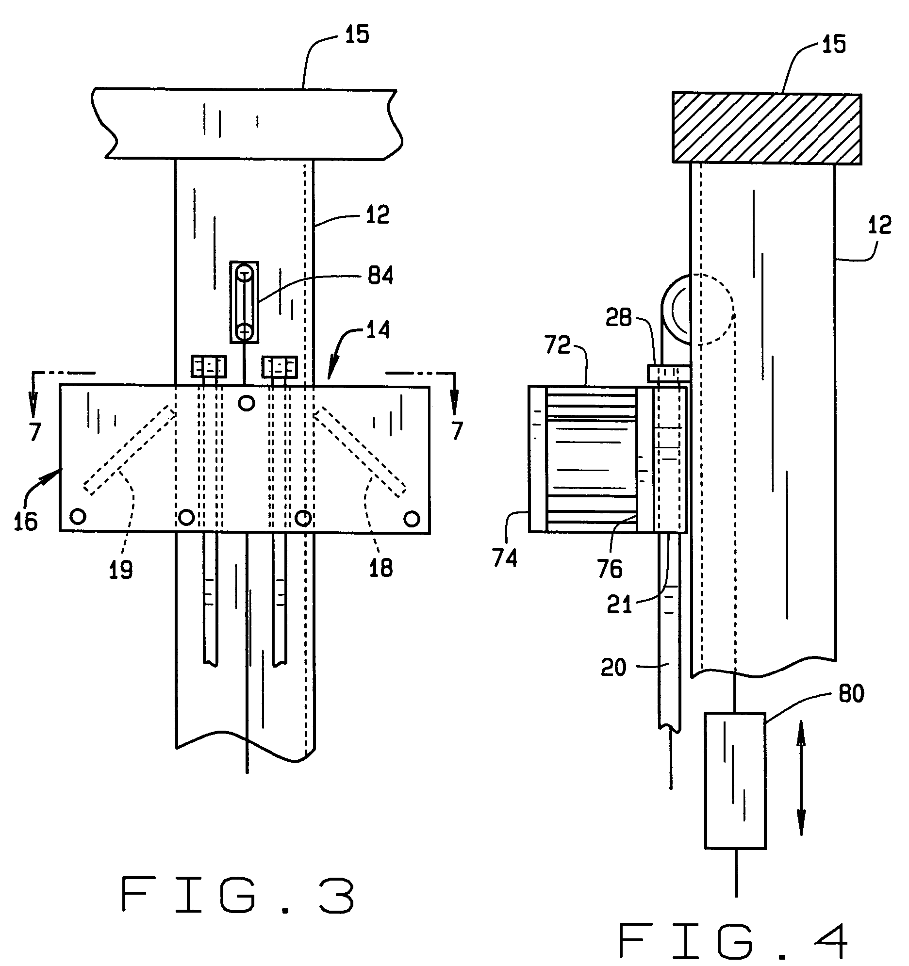
"The present invention is a projection microscope that provides excellent magnification and resolution without the need for complicated parts. It has easy-to-operate adjustments and can be used in conjunction with commercially available video cameras to produce a large image. The microscope has a sturdy support structure for the component parts, especially the stage and the optical and illumination systems. It includes an elongate support member, a stage assembly, a light emitting means, a light receiving means, a mirror assembly, an objective lens assembly, a secondary lens, a collimator assembly, and a guidance system. The microscope is relatively easy and inexpensive to manufacture, install, and operate, and is particularly effective for its intended purpose."

Problems solved by technology

There have been many attempts to improve on the basic microscope discussed above but most improvements, particularly to the optical system tend to be very expensive, with little gained for the high cost.

Method used


Image

  • Projection microscope
  • Projection microscope
  • Projection microscope

Examples


Embodiment Construction

[0034]Nomenclature The terms of art used in the description are provided below[0035]Light Source Any source of light with operator control of intensity and light distribution.[0036]Collimator A collimator provides a means of selecting and concentrating light from the light source into a uniform beam or column of light directed perpendicularly at the specimen holding stage.[0037]Collimator Output Conditioning Lens An optional lens system selected by the operator placed between the collimator and the specimen. This lens system may be moved a selected distance from the specimen to control the location and distribution of light at the specimen level to achieve the desired image quality when viewed at a monitor screen.[0038]Stage The stage is a platform for holding the specimen on a plane perpendicular to the light directed at the specimen. The operator can move the specimen in the x and y axes of the plane to position the specimen.[0039]Objective Lens The objective lens is selected by t...


PUM


Abstract

This projection microscope (10) includes an elongate support member (12) carrying a stage assembly (22) between its ends, the stage assembly (22) having opposed sides and an associated specimen holder (28). A light emitting source (24) and a light receiving point (26) are spaced from the stage assembly (22), the linear distance between them defining an optical path (100). An adjustable mirror assembly (18, 19) is carried at one end of the support member (12) including laterally spaced first and second mirrors (18, 19), the first mirror (18) receiving light from the light emitting source (24) and the second mirror (19) directing light to the light receiving point (26). An objective lens assembly (30) is disposed between the stage assembly (22) and the first mirror (18), and a secondary lens (40) is disposed between the second mirror (19) and the light receiving point (26).

Description

BACKGROUND OF THE INVENTION[0001]This invention relates generally to microscopes and particularly to a projection microscope having high magnification and resolution.[0002]The device known as a microscope has been available since about 1650. Essentially, such devices provide a means of making objects appear much larger than they are and are particularly useful for the study of biological specimens. They consist of an illumination source that lights the specimen, a stage that holds the specimen in place and, above all an optical system that provides the requisite degree of magnification, that is, the size of the image of the specimen compared with the actual size of the specimen. The image is viewed by the human eye or a technological substitute for the eye, such as a video camera.[0003]Conventional compound microscopes comprise essentially of two optical elements, namely, an objective lens and an ocular lens. The objective lens forms a real, aerial inverted image at some point along...

Claims


Application Information

Patent Timeline
Patent Type & Authority Patents(United States)
IPC IPC(8): G02B21/00G02B21/06G02B21/08G02B21/26G02B21/36
CPCG02B21/0008G02B21/06G02B21/086G02B21/26G02B21/361
Inventor BOGLE, ALAN W.BOGLE, RUSSELL H.
Owner QUIKMATE
Learn More