
Collapsible lens mount systems

a technology of collapsible lenses and mount systems, which is applied in the field of optical imaging systems, can solve the problems of limited space reduction, axially collapsible compound lenses are not always suitable choices, and smartphone photographers have little choice for imaging variance, etc., and achieve excellent magnification, low distortion, and high performance imaging

Active Publication Date: 2019-10-08
ALMALENCE
View PDF7 Cites 0 Cited by
  • Summary
  • Abstract
  • Description
  • Claims
  • Application Information

AI Technical Summary

Benefits of technology

The system achieves high magnification, resolution, and low distortion in imaging mode while minimizing space in storage mode, overcoming the limitations of traditional axially collapsing lenses and providing a compact, reliable imaging solution for space-constrained devices.

Problems solved by technology

This necessitates a limit with regard to the amount of space reduction.
For systems which are critical with regard to thickness, these axially collapsing compound lenses are not always a suitable choice.
The fixed focal length tends to be highly restrictive leaving smartphone photographers little choice for imaging variance.
Nevertheless, smartphone cameras do have very good optics that consume very little space—albeit with limitations.
However use of these systems also come with significant drawbacks and shortcomings.
Lens systems which add on to the external portion of a smartphone tend to not cooperate perfectly with the non-removable optics.
Further, dirt tends to interrupt the optical path and easily collects in the system and is hard to clean.
Removable lenses that are not integrated with the smartphone tend to be easily lost or forgotten and left behind.
Other problems render these imperfect extensions less than ideal.
While systems and inventions of the art are designed to achieve particular goals and objectives, some of those being no less than remarkable, these inventions of the art have nevertheless include limitations which prevent uses in new ways now possible.
Inventions of the art are not used and cannot be used to realize advantages and objectives of the teachings presented herefollowing.

Method used


Image

  • Collapsible lens mount systems
  • Collapsible lens mount systems
  • Collapsible lens mount systems

Examples


Embodiment Construction

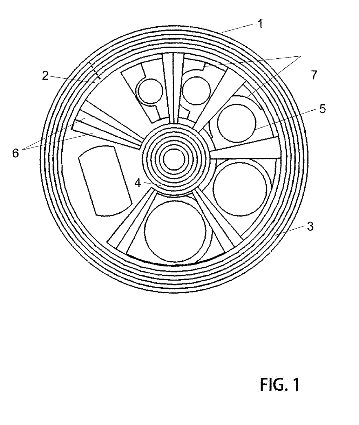
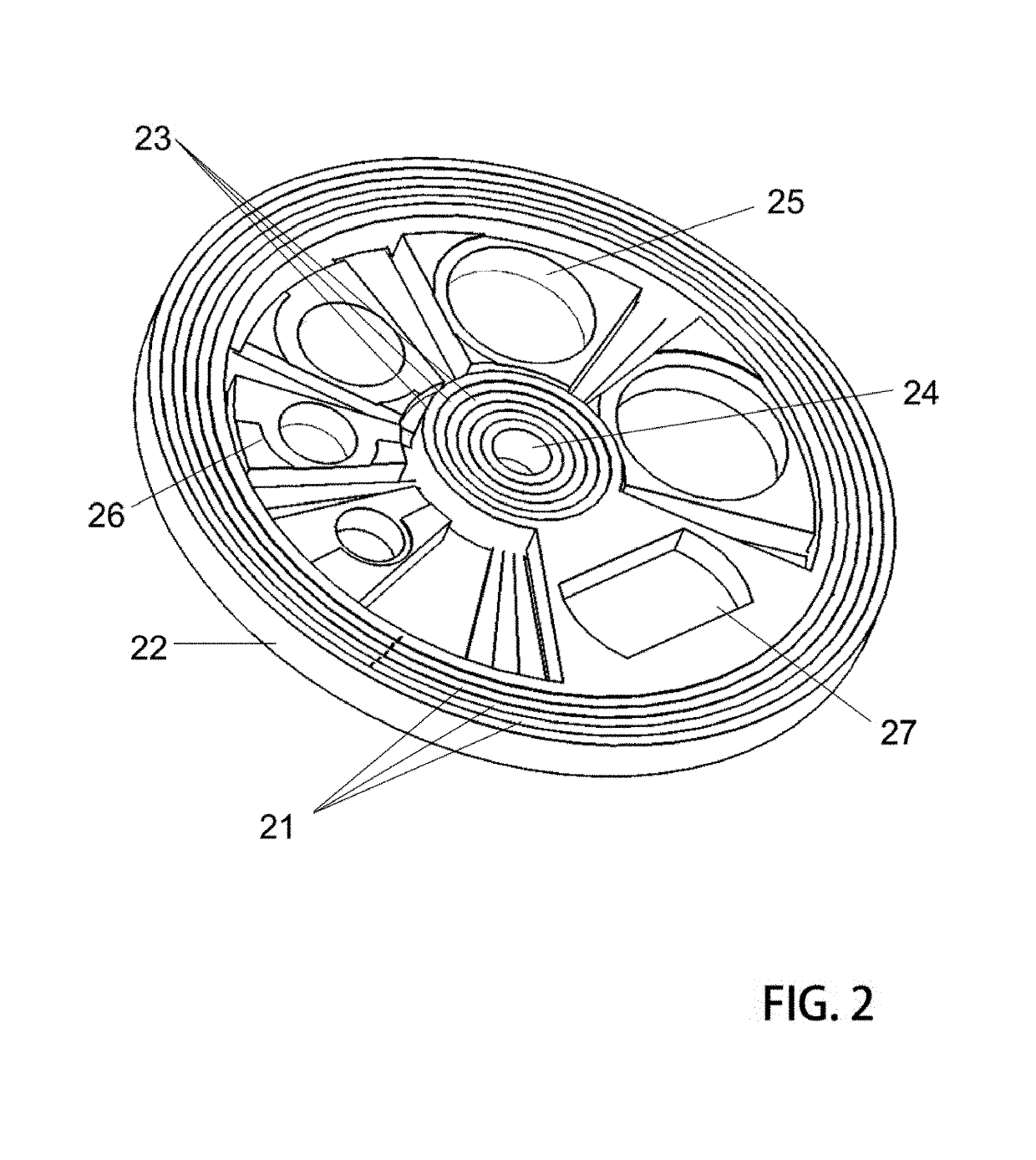
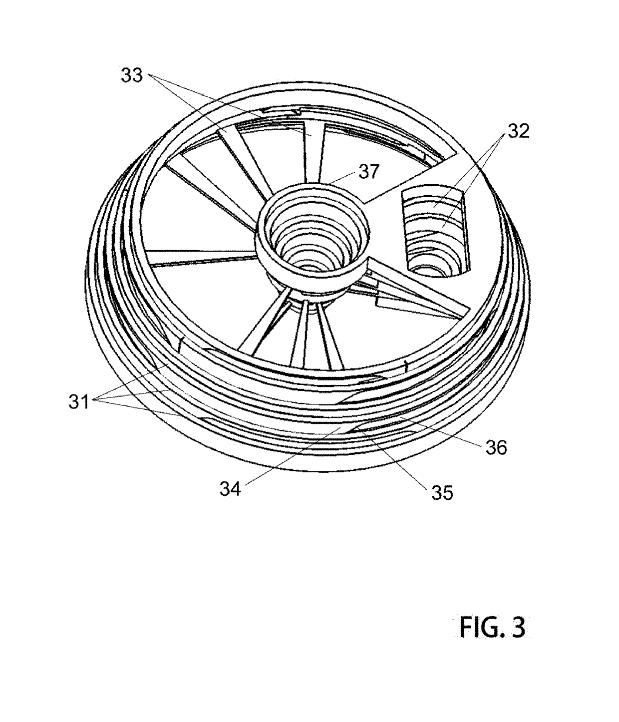
[0035]In accordance with each of preferred embodiments of the invention, dual mode lens mount systems are provided. Lens mount systems of these teachings include those having an imagine mode in one configuration and a storage mode in another configuration. It will be appreciated that each of the embodiments described include an apparatus and that the apparatus of one preferred embodiment may be different than the apparatus of another embodiment. Accordingly, limitations read in one example should not be carried forward and implicitly assumed to be part of an alternative example.

[0036]Collapsible lens systems presented herein are unique in that they cooperate particularly well in applications that demand a very thin profile when in a storage mode. Because special mechanical arrangements of interlocking parts permits a collapsing action that is characterized as helical or ‘off-axis’ a highly efficient high performance imaging means is realized. Individual lenses of a compound lens are...


PUM


Abstract

Systems are presented with special mechanical means to switch a set of lens elements to form a compound lens from a storage position to an imaging position. In the storage mode, these arrangements offer highly efficient space saving schemes suitable for use in application where space is a premium. In the imaging mode, a plurality of lens singlets are brought together on a common imagine axis whereby they operate to form very high quality images at a single image plane. Singlet lenses are held in a lens mount device of a disk element. A plurality of similar cooperating disk elements move against adjacent coupled disks to cause well-regulated desirable motion and positioning. Specifically, portions of the disk include a cam system which permits smooth movement as disk elements are counter rotated with respect to each other thus driving the preferred positioning.

Description

BACKGROUND OF THE INVENTION[0001]This patent application stands on its own as an original new and initial application for patent without continuation dependence from any other earlier filed applications.Field[0002]The following invention disclosure is generally concerned with optical imaging systems and specifically concerned with very compact optical imaging systems having integrated therewith a high performance collapsible function.Related Systems[0003]Imaging systems have been arranged to support improved imaging performance during use of a camera and improved portability when the camera is not being used in an active imaging mode—i.e. during transport.[0004]In one example, the very well known and popular Nikon camera company uses a Nikon F-mount system on their single lens reflex cameras. While a primary purpose is for interchangeable lenses, the F-mount also, allows lenses to be removed from camera bodies for improved ease of transport. A camera body fits into a much smaller sp...

Claims


Application Information

Patent Timeline
Patent Type & Authority Patents(United States)
IPC IPC(8): G02B15/14G02B7/10G03B17/12G02B13/12G02B7/16G03B17/04
CPCG02B13/12G02B7/10G02B7/16G03B17/04G02B15/14G03B17/12G03B2205/0092G02B7/021G03B2205/00
Inventor SHMUNK, DMITRY VALERIEVICH
Owner ALMALENCE
Learn More