Computer tomograph comprising energy discriminating detectors

a detector and computer technology, applied in tomography, instruments, nuclear engineering, etc., can solve the problems of major errors in the approximate determination of the medium quantum energy per x-ray quantum, damage to biological tissues, and severe suppression of low-energy components of x-ray radiation spectrum

Inactive Publication Date: 2006-11-21
SIEMENS HEALTHCARE GMBH
View PDF10 Cites 25 Cited by
  • Summary
  • Abstract
  • Description
  • Claims
  • Application Information

AI Technical Summary

Benefits of technology

[0018]An object of an embodiment of the present invention is to provide a computer tomograph and a method for verification of X-ray radiation by way of a detector unit which includes large number of detectors and in which an adverse effect on the measurement result caused by scattered radiation quanta or hardening effects is easily and reliably avoided.

Problems solved by technology

The use of X-ray radiation has the disadvantage that, beyond a certain dose, it can damage biological tissue.
When the measurement X-ray radiation emitted from a radiation source passes through a measurement object, the X-ray radiation is subject in some cases to severe suppression of low-energy components of its spectrum, depending on the materials it is passing through and on the length of the beam path through the materials.
Particularly in areas in which different materials in the measurement object being analyzed are adjacent to one another (for example bone edges), the approximate determination of the medium quantum energy per X-ray quantum is subject to major errors, despite numerical corrections.
This leads to a considerable deterioration in the contrast in the measurement result obtained from the detectors in the detector unit.
The provision of a scattered radiation grid accordingly means that a certain percentage of the radiation quanta of measurement X-ray radiation which is emitted for measurement purposes is absorbed in the scattered radiation grid, and can thus no longer be detected by the detectors.
In medical applications, this unavoidably leads to an increased patient dose.
Furthermore, the scattered radiation can frequently also not be sufficiently well suppressed by the provision of a scattered radiation grid.

Method used


Image

  • Computer tomograph comprising energy discriminating detectors
  • Computer tomograph comprising energy discriminating detectors
  • Computer tomograph comprising energy discriminating detectors

Examples


Embodiment Construction

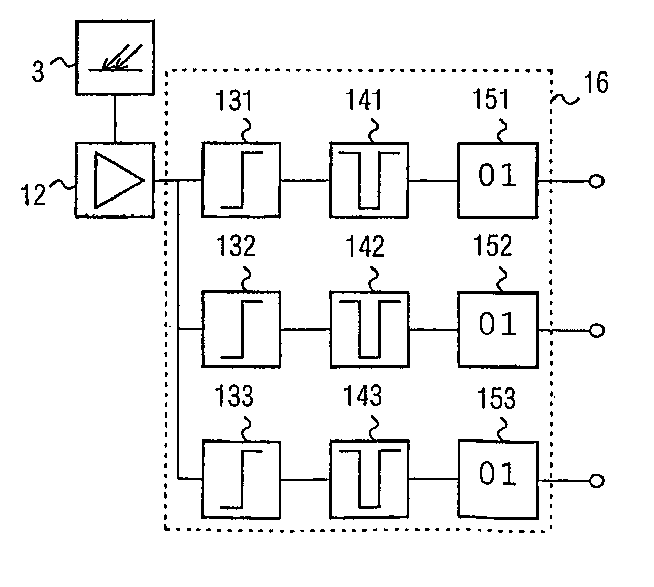
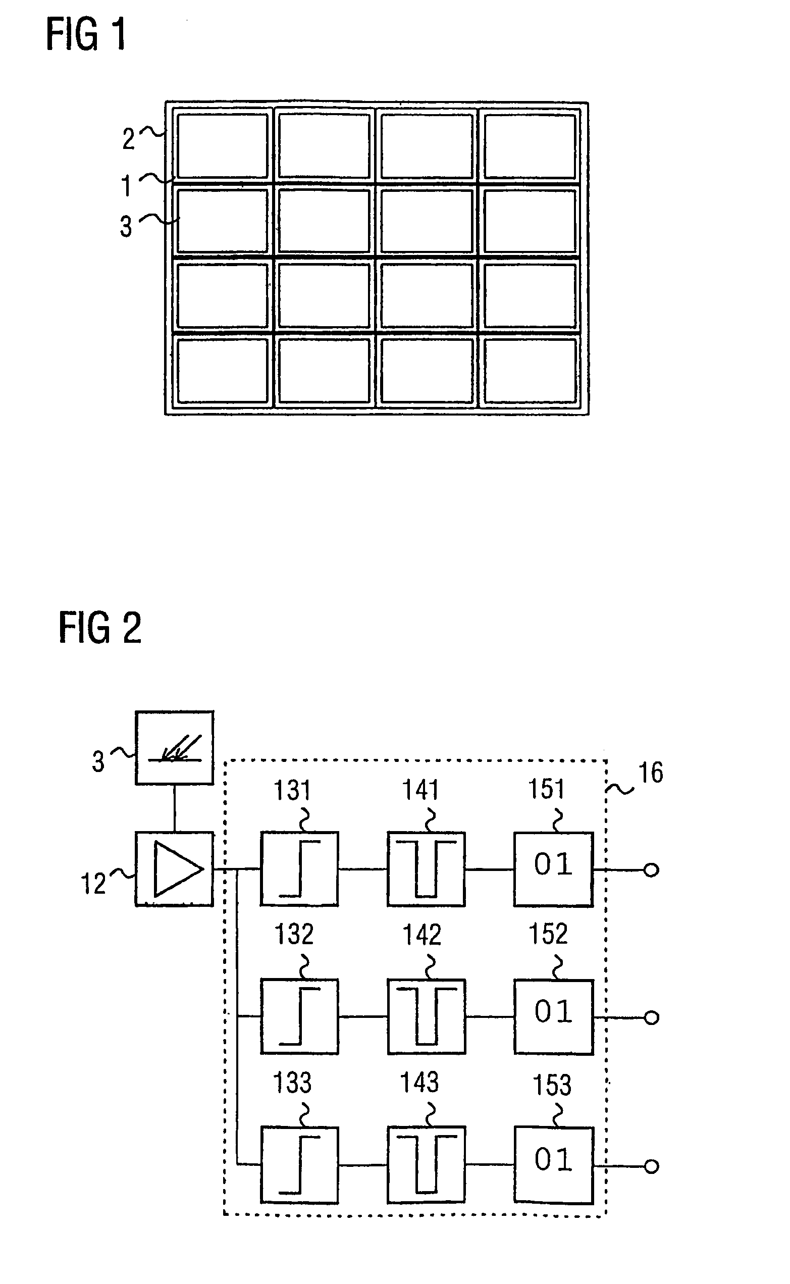
[0066]FIG. 1 shows a detector unit, which includes a large number of detectors, for a computer tomograph for verification of X-ray radiation.

[0067]The individual detectors 1 in the detector unit 2 are each designed to be the same, and each have a receiving area 4 for X-ray radiation.

[0068]In the illustrated preferred embodiment, the receiving areas 4 of the detectors have a scintillator material, in which impinging X-ray quanta are converted to light. In this case, the number of photons which are produced by a received X-ray quantum is approximately proportional to the quantum energy of the received X-ray quantum. In FIG. 1, bismuth germanium oxide (Bi4Ge3O12) is used as the scintillator material. However, alternatively, gadoliniumoxysulfide (Gd2O2S) ceramic or lutetium oxyorthosilicate (Lu2SiO5) are also highly suitable owing to the speed of these scintillator materials.

[0069]However, alternatively, the receiving areas 3 of the detectors may also be formed from cadmium zinc telluri...


PUM

PropertyMeasurementUnit
quantum energyaaaaaaaaaa
energyaaaaaaaaaa
timeaaaaaaaaaa

Abstract

The invention relates to a computer tomograph comprising a detector unit (2) consisting of a plurality of detectors (1) for identifying X-ray radiation (40). According to the invention, the individual detectors (1) of the detector unit (2) are configured to receive incident quanta of the X-ray radiation (40) and to record the received X-ray radiation (40), both in terms of its intensity and in terms of the quantum energy of the individual X-ray quanta of the received X-ray radiation (40). The invention also relates to a corresponding method for identifying X-ray radiation by means of a computer tomograph that comprises a detector unit (2) consisting of a plurality of detectors (1).

Description

[0001]This application is the national phase under 35 U.S.C. § 371 of PCT International Application No. PCT / DE03 / 00818 which has an International filing date of Mar. 13, 2003, which designated the United States of America and which claims priority on German Patent Application number DE 102 12 638.0 filed Mar. 21, 2002, the entire contents of which are hereby incorporated herein by reference.FIELD OF THE INVENTION[0002]The present invention generally relates to a computer tomograph and to a method for verification of X-ray radiation by use of a detector unit which includes a large number of detectors.BACKGROUND OF THE INVENTION[0003]Examinations are carried out with the aid of computer tomographs in many medical problem situations. Examinations such as these are also carried out for test purposes in a number of machine construction fields, in particular in materials science and flight safety.[0004]X-ray radiation is used in this case because these solid bodies, for example non-metall...

Claims


Application Information

Patent Timeline
Patent Type & Authority Patents(United States)
IPC IPC(8): A61B6/03H05G1/64G01N23/04
CPCA61B6/032
Inventor HEISMANN, BJORNVON DER HAAR, THOMAS
Owner SIEMENS HEALTHCARE GMBH
Why Eureka
Try Eureka