Moving flange for passenger conveyors

Inactive Publication Date: 2006-11-28
OTIS ELEVATOR CO
View PDF4 Cites 11 Cited by
  • Summary
  • Abstract
  • Description
  • Claims
  • Application Information

AI Technical Summary

Benefits of technology

[0016]Preferably all the bridges are attached to the drive chain in this manner. The resilient locking element provides for a clearance-free attachment of the bridge. Moreover, this element can be made so as to provide a clearly audible noise once the bridge safely snaps in. This avoids any incorrect mount by the service technicians. The resilient locking element can be constructed so as to be operable by a simple tool, for example a screw driver, etc. Moreover, no loose parts are required.
[0017]Preferably, the pin is attached to a chain link, while the socket is attached to the bridge. With such a construction, the bridge can easily be slid onto the pin even without any tools. Preferably the pin is threaded into the chain link. This is a relatively easy mount. The chain link is to be machined very intensively anyhow after die casting, as it has to keep close tolerances, thus machining a thread bore is not substantially increasing costs and machining time. A “one-time” thread connection is a relatively secure connection for the link. Moreover, it is possible to further secure this thread connection by way of adhesive, since it is not necessary to untighten the pin subsequently. It is also possible to attach the pin by any different way to the chain link, for example by way of a press fit, adhesive only, etc. Prefer

Problems solved by technology

While the moving flange greatly enhances the safety of passenger conveyors as compared to conventional designs, it poses new problems for the engineers in this field.
One of the problems which arise in this type of conveyors is to provide a moving flange which is thin and st

Method used


Image

  • Moving flange for passenger conveyors
  • Moving flange for passenger conveyors
  • Moving flange for passenger conveyors

Examples


Example

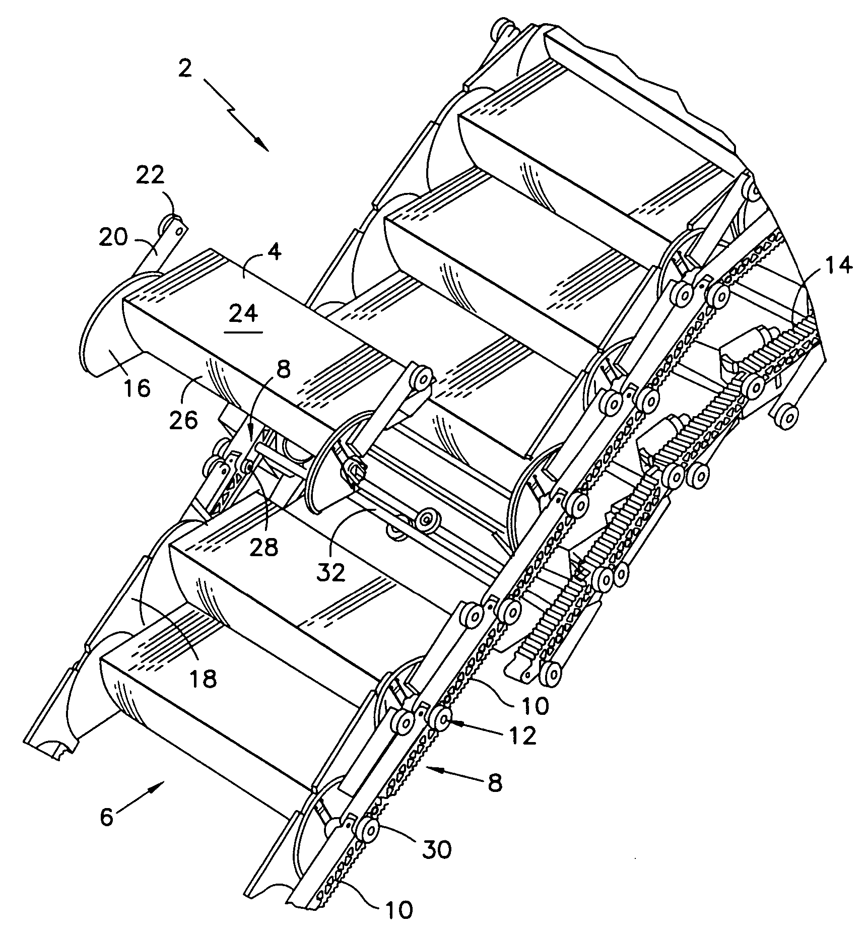
[0028]FIG. 1 shows an inventive passenger conveyer 2 with an endless passenger conveyer band 6 that is composed of several interconnected tread elements 4. The tread elements 4 are connected to drive chains 8 that are respectively arranged laterally of the tread elements 4 and consist of a series of chain links 10. The chain links 10 are connected to one another at pivots 12. The passenger conveyer 2 is driven by a conveyer drive, for example a linear drive, etc. The drive engages a toothing 14 of the chain links 10.

[0029]In FIG. 1 the shown passenger conveyer 2 consists of an escalator. On escalators, the passenger conveyer band 6 is referred to as a step band, and the tread elements 4 are referred to as steps. FIG. 1 mainly shows the step band 6, the drive chain 8 and chain and step rollers 30 and 22, respectively. Thus, roller guide tracks, etc. are not shown in FIG. 1. One of the steps 4 is removed from the step band 6. For the particular construction which allows for easy remov...


PUM


Abstract

Passenger conveyor (2) including an endless conveyor band (6) comprised of a plurality of tread elements (4) connected to and driven by a drive chain (8) at each lateral edge thereof, a moving flange moving in use together with the conveyor band (6), the moving flange being comprised of a plurality of discs (16) attached to the tread elements (4) and a plurality of bridges (18) each attached alternating between two consecutive discs (16), wherein a groove and tongue (70) engagement is provided between bridge (18) and disc (16), characterised in that an insert (64) made of a plastic material is provided between bridge (18) and disc (16).

Description

FIELD OF THE INVENTION[0001]The present invention relates to passenger conveyors including an endless conveyor band.DESCRIPTION OF THE RELATED ART[0002]Such a passenger conveyor is known for example from WO 02 / 44072 A1. Escalators and moving walkways are typical examples of such passenger conveyors. An escalator usually contains a series of movable interconnected tread elements that are referred to as “steps” and driven around upper and lower chain reversing wheels or other reversal constructions by a driving motor. These interconnected steps are referred to as a passenger conveyor band or step band. Similarly, moving walkways contain several interconnected pallets that are also driven such that they revolve around two chain reversal constructions. In moving walkways of this type, the passenger conveyor band is usually referred to as a pallet band.[0003]With the passenger conveyor of WO 02 / 44072 a moving flange is provided at each lateral edge of the tread element extending upwards ...

Claims


Application Information

Patent Timeline
IPC IPC(8): B66B23/12B66B23/18
CPCB66B23/12B66B29/02B66B23/18
Inventor STUFFEL, ANDREASMEYER, HELMUTCHEN, YANGYING ANNE
Owner OTIS ELEVATOR CO
Why Eureka
Try Eureka