Nozzle assembly with fuel tube deflector

a technology of fuel nozzles and deflectors, which is applied in the field of injectors, can solve the problems of less desirable technique, time-consuming process for manufacturing and assembly of such a heatshield, and thermal stress in the injector, and achieves the effects of reducing thermal stress, reducing pressure drop, and minimizing disruption of flow

Active Publication Date: 2006-11-28
PARKER INTANGIBLES LLC
View PDF6 Cites 40 Cited by
  • Summary
  • Abstract
  • Description
  • Claims
  • Application Information

AI Technical Summary

Benefits of technology

[0007]The present invention overcomes at least some of the above drawbacks and prevents or at least reduces the thermal stresses associated with the introduction of cooler inlet fuel into the swirler body of a fuel injector. According to the present invention, a deflector is located at the downstream end of the fuel discharge tube, and deflects all or a portion of the incoming fuel into the annular fuel delivery channel, where the fuel then flows evenly around the channel to the flow slots. The deflector prevents direct impact of the cooler fuel on the exposed swirler body, but does not detrimentally effect the flow of fuel into the flow slots in the swirler.
[0008]According to one embodiment of the invention, the deflector is formed by a tab or other integral portion of the heatshield. In a second embodiment, the deflector may be a separate piece fixed such as by brazing or welding to the heatshield, or to the swirler body itself. In either embodiment, the deflector is adjacent or proximate the discharge end of the fuel delivery tube, and has a dimension or design that minimizes disruption of the flow through any of the flow slots that are covered by the deflector. In one form of the invention, the deflector may have a relatively small circumferential extent, such that the deflector covers only one or at most two flow slots, and fuel can easily pass around the end of the deflector and back to the covered flow slot(s) with negligible pressure drop. In another form of the invention, the deflector can have a more substantial circumferential extent, and include flow openings or slots along its extent (spaced away from the area directly across from the discharge end of the inlet tube) that allow a portion of the fuel to flow inwardly of the deflector into the otherwise covered flow slot(s). According to yet another form of the invention, a space or gap can be provided between the side(s) of the deflector and the inner walls of the annular channel, to allow a portion of the fuel to flow around the sides of the deflector to the covered flow slots.
[0009]As should be appreciated, the deflector in any of the embodiments is a simple, robust component that is relatively easy to manufacture or fabricate, and which prevents or at least minimizes the thermal stresses associated with the cooler fuel entering the hotter swirler body of the injector. Further features of the present invention should become apparent to those skilled in the art upon reviewing the following specification and attached drawings

Problems solved by technology

However as can be appreciated, the manufacture and assembly of such a heatshield then becomes a time-consuming process, and the heatshield then requires careful installation into the nozzle to align the openings in the heatshield with the fuel slots in the swirler.
In all, this is a less desirable technique than using a C or U-shaped heatshield.
The cold fuel from the delivery tube creates a localized “cold spot” in the swirler body across from the delivery tube, which can cause thermal stress in the injector.
Such stress is undesirable in many instances.

Method used


Image

  • Nozzle assembly with fuel tube deflector
  • Nozzle assembly with fuel tube deflector
  • Nozzle assembly with fuel tube deflector

Examples


Embodiment Construction

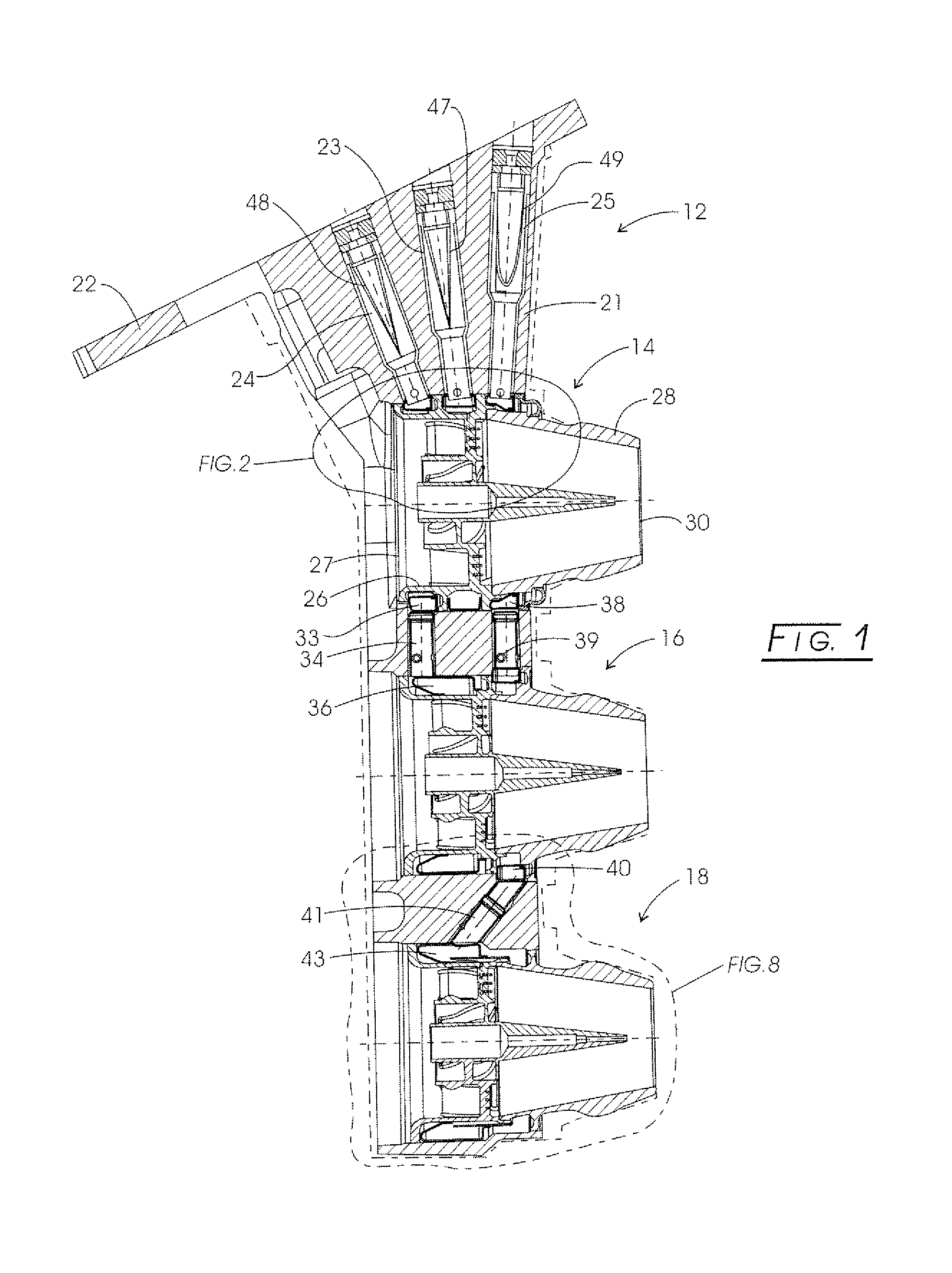
[0019]Referring to the drawings, and initially to FIG. 1, a fuel injector assembly constructed according to the principles of the present invention is indicated generally at 12. The injector assembly is illustrated as having three nozzle assemblies, indicated generally at 14, 16 and 18, however it should be appreciated that this is for exemplary purposes only, and that the injector could have one, two or any number of nozzle assemblies that receive fuel from a manifold. Also, while a particular nozzle assembly will be described below, it should also be appreciated that this is also for exemplary purposes only, and that the present invention could be appropriate for a wide variety of nozzle structures and configurations.

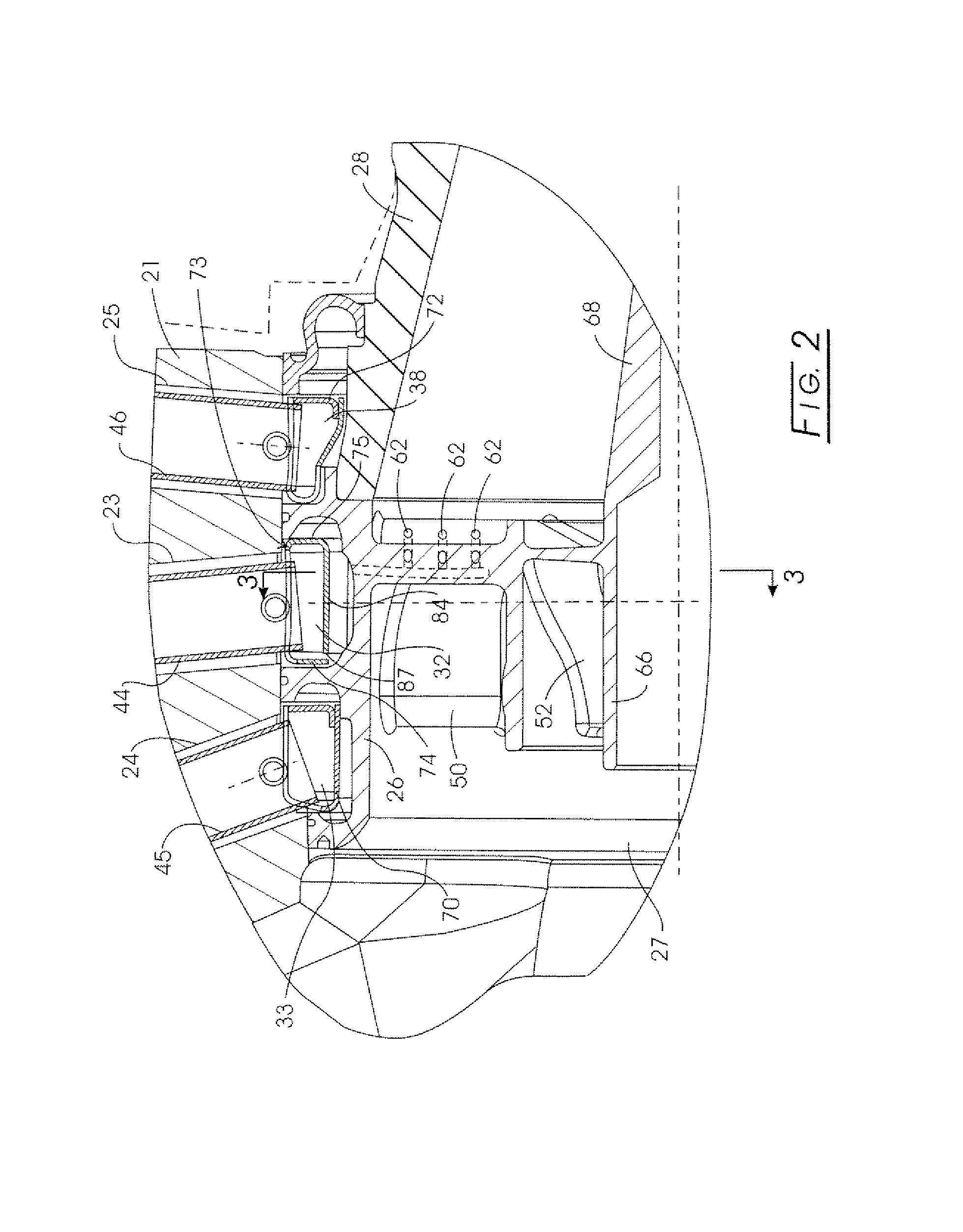
[0020]In any case, the injector assembly 12 includes an injector body or stem 21 with a flange or mounting bracket 22, for mounting the injector to an upstream wall of a combustion chamber in a turbine engine; and a series of fuel passages 23, 24, 25, individually flu...


PUM


Abstract

A deflector at the downstream end of a fuel tube deflects incoming fuel into an annular fuel channel in a fuel swirler of an injector. The deflector prevents direct impact of the cooler fuel on the exposed walls of the swirler body. The deflector can be formed by a tab or other integral portion of the heatshield, or as a separate piece fixed to the heatshield or swirler body. The deflector minimizes disruption of flow through any flow slots that are covered by the deflector, and may have i) a relatively small circumferential extent, such that the deflector covers only a few flow slots, ii) flow openings or slots that allow a portion of the fuel to flow inwardly of the deflector into the otherwise covered flow slot(s), or iii) a space or gap between the side(s) of the deflector and the inner walls of the annular channel.

Description

CROSS-REFERENCE TO RELATED CASES[0001]The present application claims the benefit of the filing date of U.S. Provisional Application Ser. No. 60 / 506,565; filed Sep. 26, 2003, the disclosure of which is expressly incorporated herein by reference.FIELD OF THE INVENTION[0002]This invention relates in general to injectors for dispensing fluids in streams or sprays, and more particularly relates to fuel nozzles for dispensing liquid or gaseous fuel for ignition in an aircraft or power generating engine.DESCRIPTION OF THE PRIOR ART[0003]When fuel flows through a delivery tube or conduit to a fuel injector in an aircraft engine, the fuel entering the nozzle from the manifold is generally significantly cooler than the surrounding injector structure. This is because the high velocity, hot compressed combustion air flowing downstream through the nozzle from the compressor is in some cases at a temperature greater than 800 degrees Fahrenheit; while the incoming fuel from the fuel tank can be at...

Claims


Application Information

Patent Timeline
Patent Type & Authority Patents(United States)
IPC IPC(8): B05B1/26B05B1/34B05B7/06F02M61/00F02M63/00B05C1/00F23R3/14F23R3/28
CPCF23R3/14F23R3/28Y02T50/675Y02T50/60
Inventor STOTTS, ROBERT E.DRAKE, BRIAN T.SCHEUERMAN, CURTIS H.PATWARI, KIRAN
Owner PARKER INTANGIBLES LLC
Why Eureka
Try Eureka