Electric seat belt retractor system

a seat belt and electric technology, applied in the field of seat belt systems, can solve the problems of increased damage or injury, shoulder seat belt systems that may not properly protect the occupant, and many occupants that fail to properly adjust the tension in the safety harness, etc., to achieve the effect of ensuring ride comfort, reducing web tension, and improving motor control

Active Publication Date: 2006-11-28
AUTOLIV ASP INC
View PDF45 Cites 45 Cited by
  • Summary
  • Abstract
  • Description
  • Claims
  • Application Information

AI Technical Summary

Benefits of technology

[0016]The present invention provides an electrical retractor which overcomes many of the limitations of the prior art. The present invention provides constant and dynamic extraction and retraction of the seat belt webbing in order to follow the occupant's motion about the vehicle. This provides substantially increased comfort to the occupant, while at the same time maintaining a high degree of safety and effectiveness.
[0019]The present invention provides a previously unknown type of secondary electromechanical feedback. Servo control is used to greatly improve motor control compared to known motor implementations. More precisely, a sensor may be mounted to an axle of a web guide lever to supply exact information about webbing dynamics. This information allows the servo amplifier to adjust the direction and speed of the retractor motor in a precise manner. Thus, minimum web tension can be achieved in the seat belt system to assure ride comfort as well as rapid response to any fast or slow changes in the webbing configuration.
[0020]Thus, in summary, during normal use the system allows the seat belt webbing to be extracted and reduces the force when worn for improved occupant comfort. When the vehicle begins to reach its limits of adhesion due to increased lateral “g” force or excessive vehicle velocity, the motor drives the mechanism described below to retract the seat belt webbing with sufficient force to pull the occupant back more firmly into the seat and to attain a more favorable position for air bag deployment in the event of a crash. The mechanism described below also provides the structural “lock-up” function necessary to support belt loading and restrain the occupant during a crash. In addition, the system of the present invention provides a fail-safe mechanism whereby in the event of the loss of electrical power, the mechanism is locked in place to provide protection to the occupant.
[0025]When the seat belt of the present invention is used, the occupant pulls the seat belt to insert the latch plate into engagement with the buckle. This pull increases tension in the seat belt. The increased tension causes the arm to pivot outward from the belt opening, toward the ninety-degree position. In response, the tension sensor activates the motor to pay out seat belt webbing. Once the tension in the seat belt returns to a lower level, for example, due to release of the seat belt or engagement of the latch and the buckle, the reduced tension and the bias of the tension sensor towards the belt opening causes the tension sensor to activate the motor to retract the seat belt. As the seat belt is retracted, the tension in the seat belt increases. Increasing the tension causes the arm to pivot to form an angle of about forty-five degrees with the belt opening. Once the arm is positioned at about forty-five degrees, the tension sensor deactivates the motor. When the arm is positioned at about forty-five degrees, a comfortable amount of tension is present in the seat belt.
[0027]In view of the foregoing, the electric seat belt retractor provides substantial advantages over conventional systems. The electric seat belt retractor senses the tension in the seat belt such that a constant bias in the direction of retraction is unnecessary. The worm wheel and sliding worm and drive shaft provide a safety lock which prevents unintentional extraction of the seat belt. Conventional locking pawls and ratchet wheels are unnecessary. Together with a simple emergency control unit and automatic locking system, the seat belt retractor provides enhanced seat belt take-up with comparatively fewer components. Stated more generally, the present invention provides enhanced structures and method for accurately controlling tension within a flexible member.

Problems solved by technology

Seat belts may also keep the driver behind the wheel and in control of the vehicle prior to an impending or potential collision, averting additional damage or injuries.
However, many occupants fail to properly adjust the tension in the safety harness once the seat belt has been fastened.
If too much slack is left in the shoulder strap portion of the webbing, the shoulder seat belt system may not properly protect the occupant.
However, in actual application, seat belt systems usually contain substantial slack, often 120 mm or more.
This is clearly not ideal in that the slack can defeat the effectiveness of the seat belt in a crash situation.
In addition, removal of slack can often cause the occupant discomfort.
This discomfort may cause an occupant to use the seat belt improperly, for example, by placing the shoulder portion behind their upper torso, or by simply not using the seat belt.
The safety features of the three-point safety harness are defeated when discomfort leads occupants to misuse or avoid using the system.
Generally, the difficulty with existing seat belt systems can be summarized as inability to adequately and dynamically adjust to the position of the occupant.
Conventional systems are unable to freely and constantly adjust and often result in uncomfortable binding if the occupant makes a substantial move.
Furthermore, most conventional systems are unable to adequately respond to pre-crash situations.
Most existing systems simply lock the belt in place, but are unable to draw the occupant back into position.
Many such systems are unable to provide crash pretensioning to restrain the occupant during an actual crash, and to allow optimum interaction with airbags and other supplemental restraint systems.
Hence, conventional seat belt systems are lacking in a number of respects, and a need exists for enhanced seat belt systems that overcome the shortcomings of the prior art.
Conventional control systems generally lack the ability to dynamically and accurately control the tension.

Method used


Image

  • Electric seat belt retractor system
  • Electric seat belt retractor system
  • Electric seat belt retractor system

Examples


Embodiment Construction

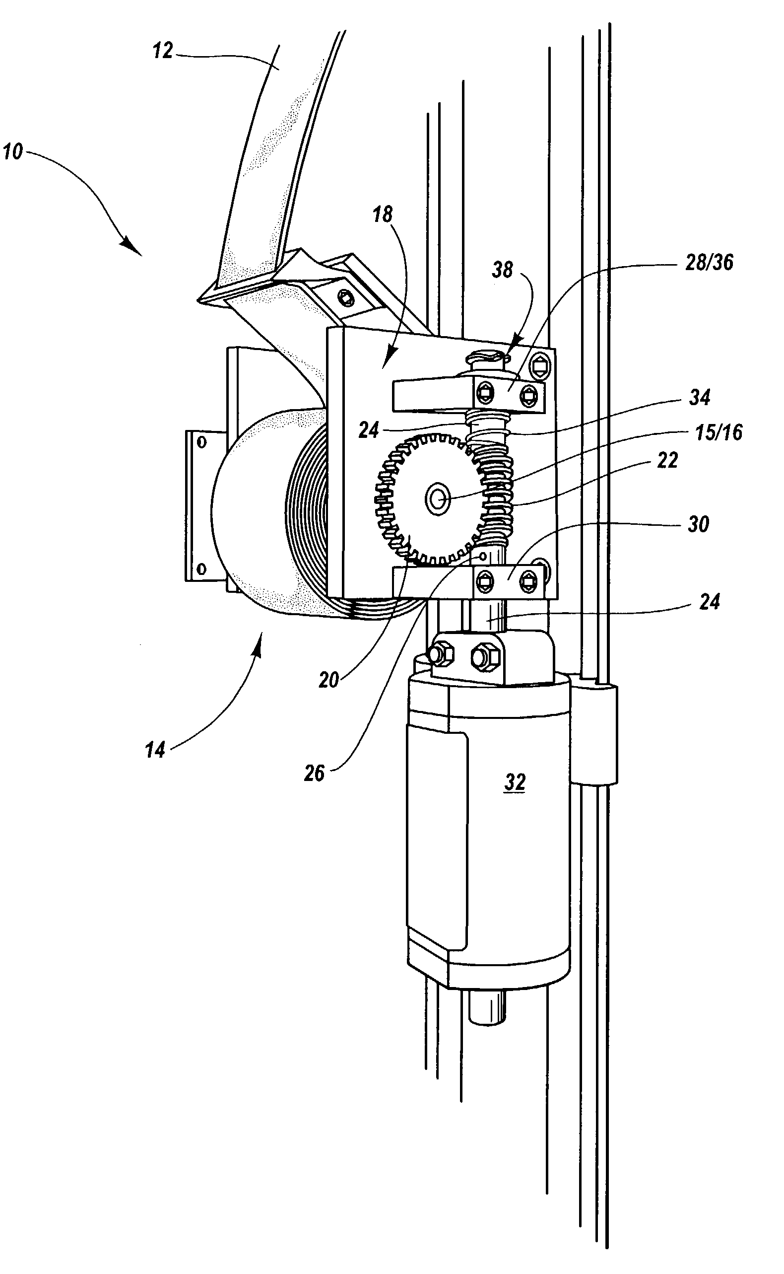
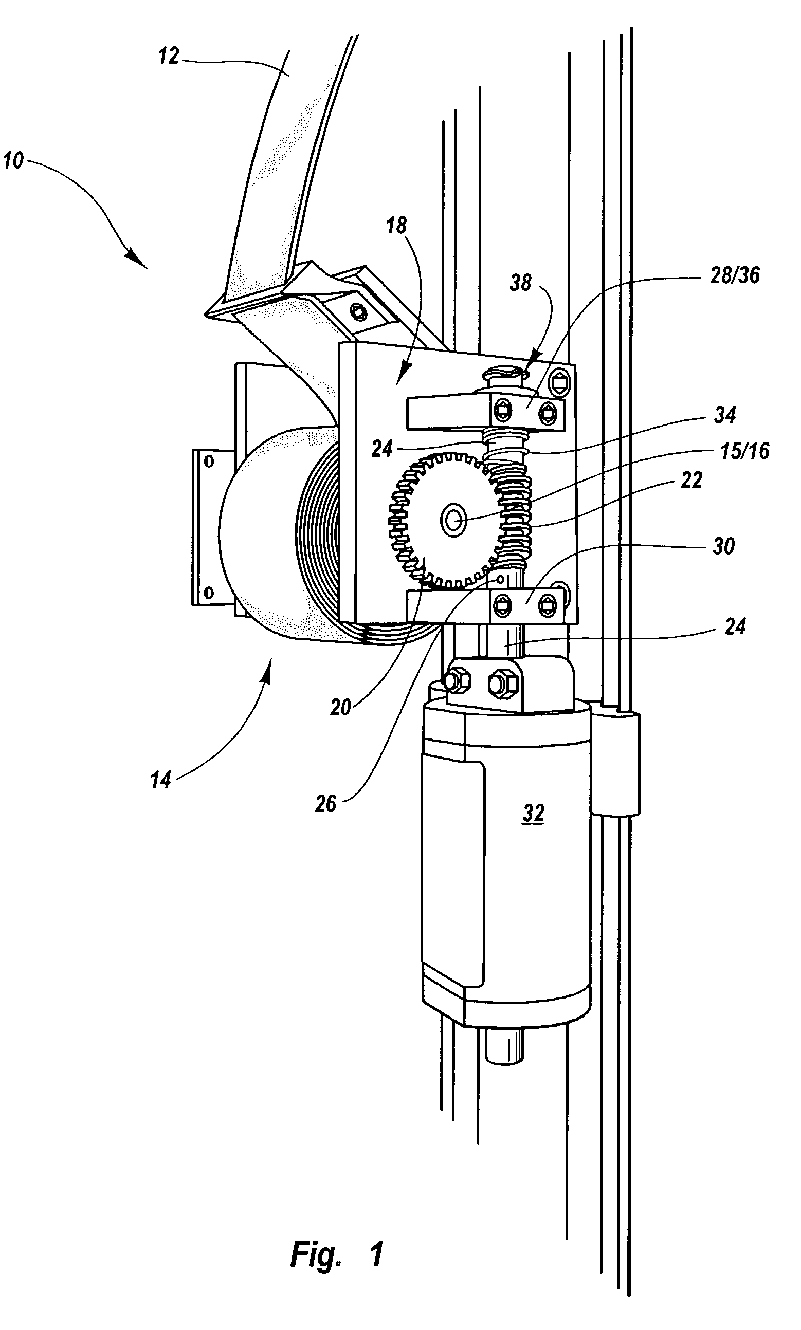
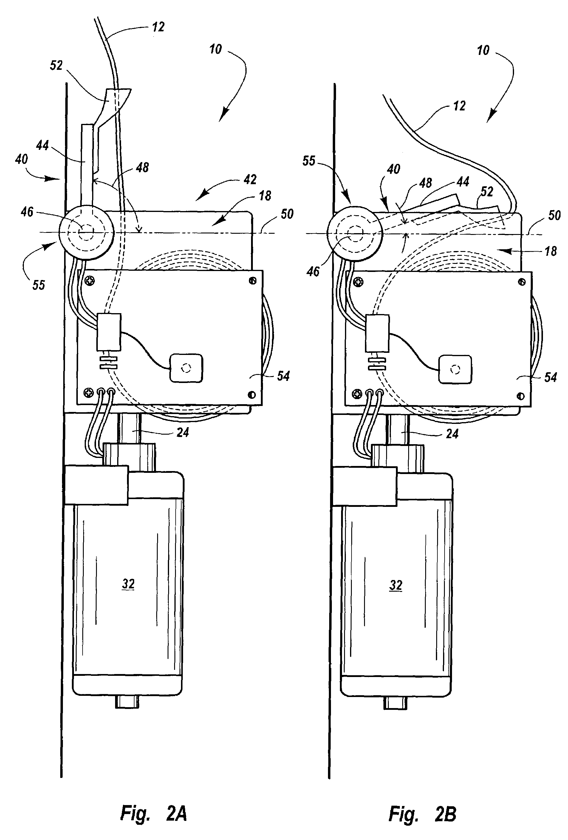
[0038]The preferred embodiments of the invention are now described with reference to FIGS. 1–6, wherein like parts are designated by like numerals throughout. The members of the present invention, as generally described and illustrated in the Figures, may be constructed in a wide variety of configurations. Thus, the following more detailed description of the embodiments of the present invention, as represented in the Figures, is not intended to limit the scope of the invention, as claimed, but is merely representative of presently preferred embodiments of the invention.

[0039]In this application, the phrases “connected to,”“coupled to,” and “in communication with” refer to any form of interaction between two or more entities, including mechanical, electrical, magnetic, electromagnetic, electromechanical and thermal interaction. The phrase “attached to” refers to a form of mechanical coupling that restricts relative translation or rotation between the attached objects. The phrases “pi...


PUM


Abstract

An electric retractor extracts and retracts a seat belt in response to tension in the seat belt. The electric retractor may include a spool rotatably attached to a retractor frame. A seat belt is wound on the spool. The spool is rotated by a motor via a worm gear system that permits limited axial motion of the worm, but generally prevents the motor from being back-driven by tension in the seat belt to prevent forced seat belt extraction. The gear system may also cut off power to the motor in the event of excessive seat belt tension to prevent further payout of the seat belt. A senses tension in the seat belt and activates the motor to retract or extract the seat belt from the retractor. An emergency control system may override the web guide control in response to abnormal vehicle dynamics to provide reversible pre-crash pretensioning and / or crash pretensioning.

Description

BACKGROUND OF THE INVENTION[0001]1. Field of the Invention[0002]The present invention relates to seat belt systems designed to protect the occupants of a vehicle during a collision. More specifically, the invention relates to an electric seat belt retractor system which is uniquely capable of protecting an occupant during normal use, pre-crash situations, and crash situations, and is capable of constantly and dynamically adjusting to the positioning of the occupant.[0003]2. Description of Related Art[0004]A “control system” may be defined as a system in which an operation is to be performed (or omitted) in a manner determined by measuring some characteristic of the system. Thus, efficient operation of the system can be maintained despite relatively unpredictable changes in the system. The present invention has application to a wide variety of control systems.[0005]There are many applications in which it may be desirable to monitor and / or automatically adjust the tension in a flexibl...

Claims


Application Information

Patent Timeline
Patent Type & Authority Patents(United States)
IPC IPC(8): B65H75/48B60R21/01B60R21/015B60R22/44B60R22/46
CPCB60R22/44B60R22/46B60R2022/4473B60R2022/4666B60R21/0155
Inventor HISHON, MICHAEL K.ENGLER, SAMUEL D.KARWACZYNSKI, KRZYSZTOF W.
Owner AUTOLIV ASP INC
Why Eureka
Try Eureka