Downhole torque-generating and generator combination apparatus

a generator combination and torque generation technology, applied in electrical equipment, dynamo-electric machines, drilling machines and methods, etc., can solve problems such as clogging of machinery and failure of downholes, and achieve the effect of avoiding excessive power outpu

Inactive Publication Date: 2006-11-28
TURBINE DYNAMICS
View PDF17 Cites 19 Cited by
  • Summary
  • Abstract
  • Description
  • Claims
  • Application Information

AI Technical Summary

Benefits of technology

[0006]There is therefore a requirement to be able to control

Problems solved by technology

Furthermore, present apparatus is vulnerable to the aggregation of mud

Method used


Image

  • Downhole torque-generating and generator combination apparatus
  • Downhole torque-generating and generator combination apparatus
  • Downhole torque-generating and generator combination apparatus

Examples


Embodiment Construction

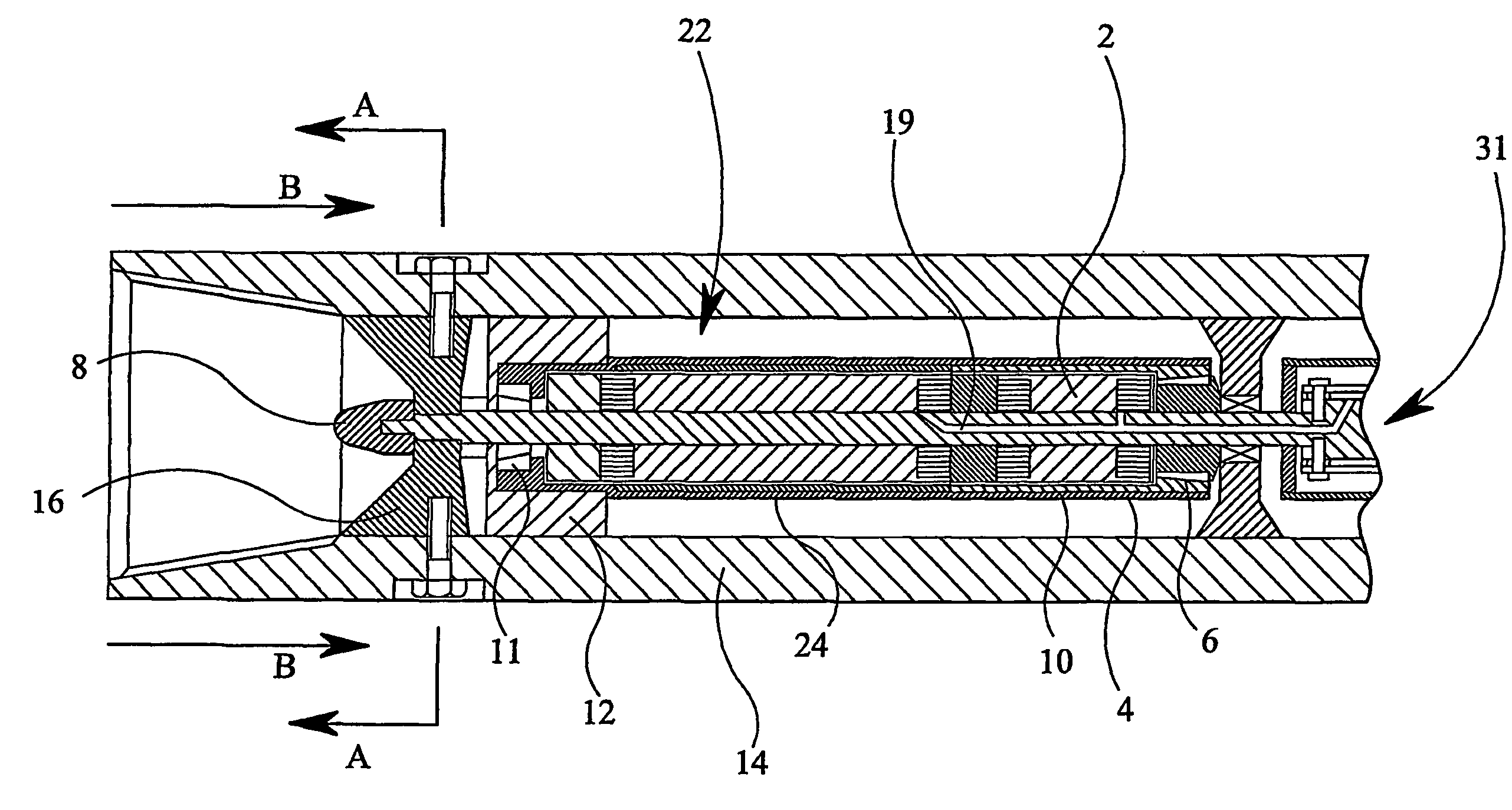
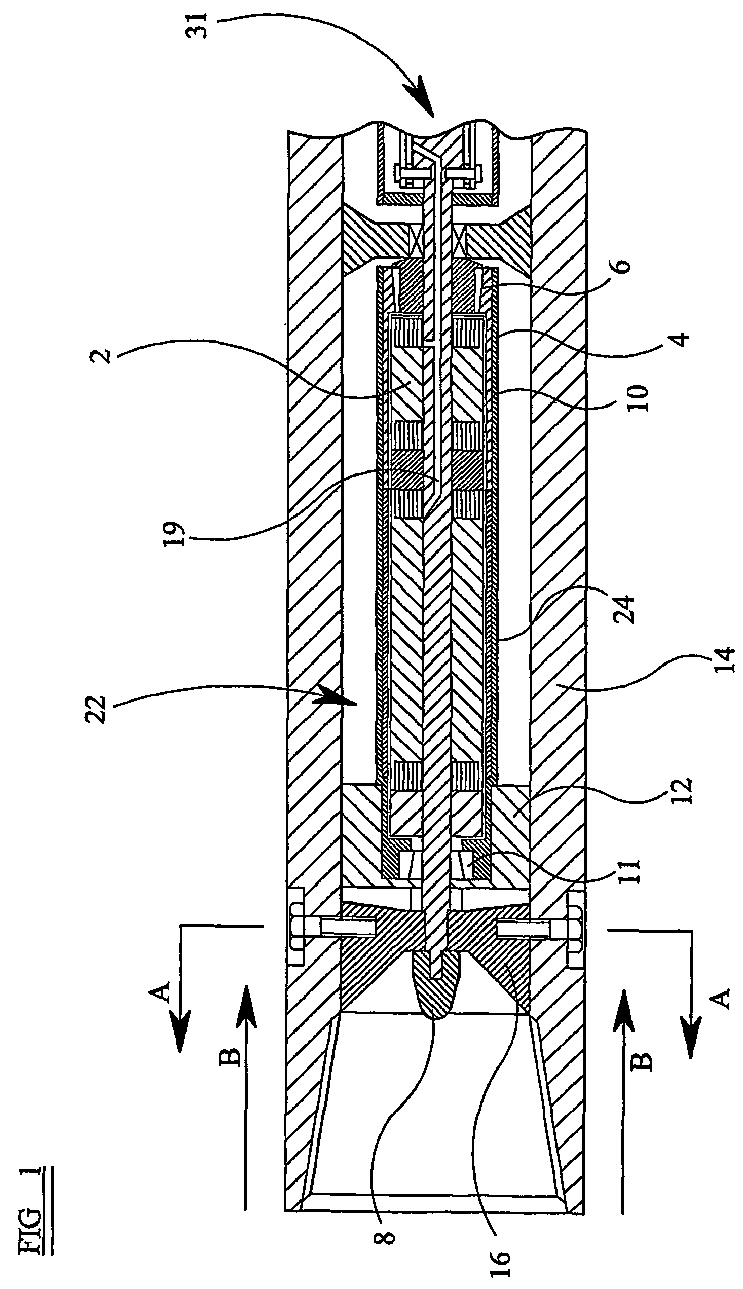
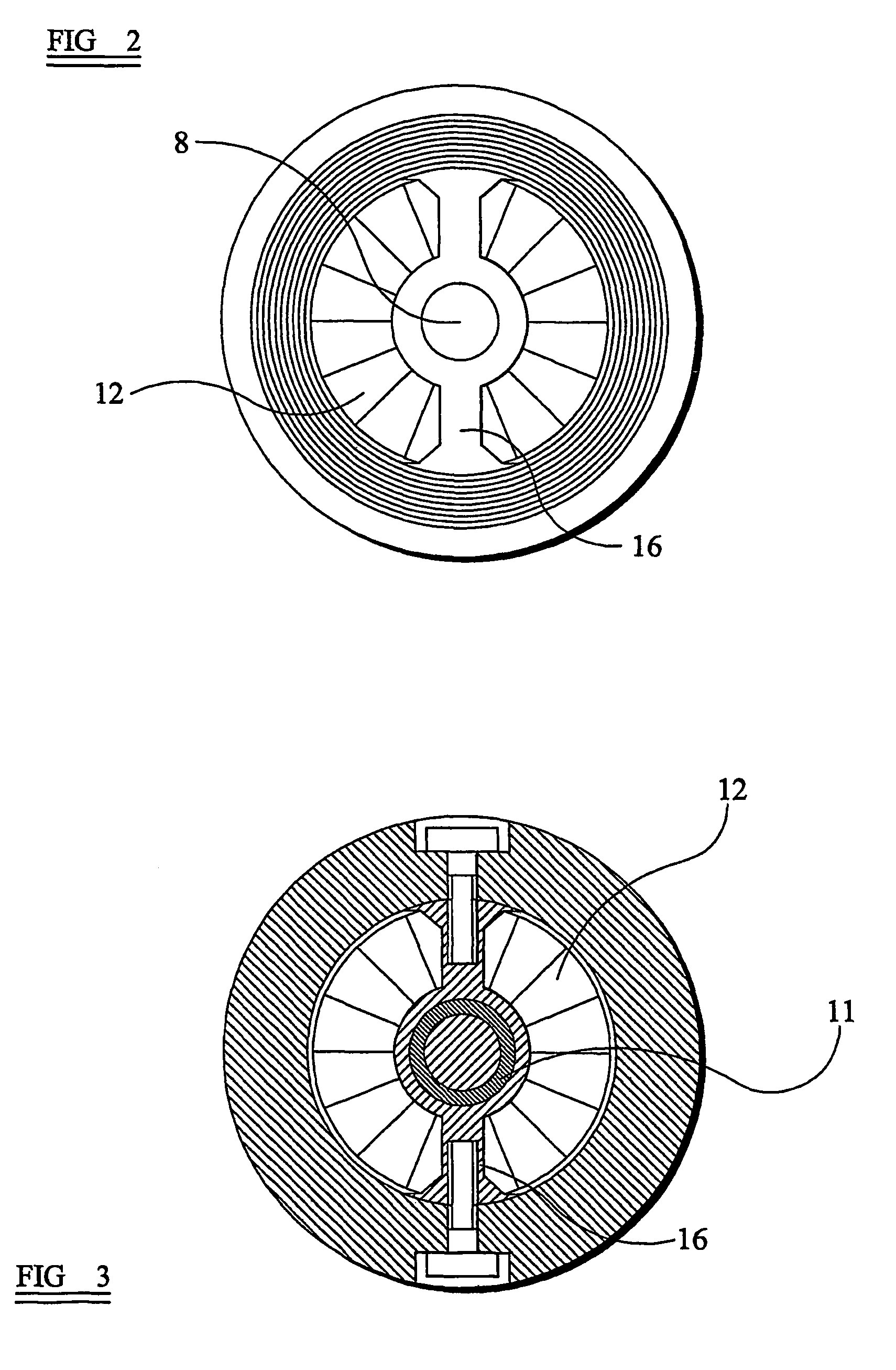
[0041]FIG. 1 shows a combination of a torque generating apparatus and alternator / generator suitable for use in drilling apparatus. The torque generating apparatus comprises a second assembly in the form of a cylindrical stator 2. The stator 2 is shown in more detail in FIGS. 4 to 7. The stator is made of magnetically soft material and is provided with stator windings 4 arranged so that, when energised, the stator 2 is magnetised as discussed below. The stator is mounted on a fixed shaft 8. Surrounding the stator is a first assembly in the form of a magnetically soft steel rotor 10. The rotor 10 is mounted on the stator 2 by way of bearings 6, 11, such as thrust bearings. The rotor / stator assembly is contained within a cylindrical housing 14 which may typically be a section of drill collar. The assembly is supported by an anchor 16 which is bolted to the housing.

[0042]A three phase alternator 22 is provided on the same shaft as the torque-generating apparatus. The alternator 22 and t...


PUM


Abstract

A combination of a torque-generating apparatus with an alternator/generator. The torque-generating apparatus comprises a first assembly (10, 25) including a generally cylindrical member of magnetically soft material and having a longitudinal axis, and a second assembly (2) arranged coaxially within the first assembly and including an electromagnetic winding (4). The first assembly (10, 25) and the second assembly (2) are rotatable relative to each other about the axis. Relative rotation between the first (10, 25) and second (2) assemblies induces a magnetic field which generates rotational torque between the first and second assemblies. Rectification means (31) is provided to convert alternating current electrical output from the alternator/generator (22) to provide D.C. current to the electromagnetic windings (4) of the torque generating apparatus to generate an electromagnetic braking effect.

Description

[0001]This invention relates to a combination of a torque-generating apparatus with a generator / alternator. More particularly, but not exclusively, the invention relates to such a combination for down hole use in drilling applications.BACKGROUND OF THE INVENTION[0002]The presently preferred power generator in oilfield exploration or extraction applications is the mud alternator because it is powerless on the surface, and therefore safe to handle, and only generates power once down hole and spinning in the mud flow. However, one of the major problems faced by both the provider and end-user of drilling equipment has been the control of impeller speed of down hole mud alternators.[0003]All mud alternators effectively run open loop and the only way to govern their speed is either to modify the flow rate of mud pumped past the impeller or to change the impeller. These methods are not always successful in controlling alternator speed and, hence, power output. An alternator that rotates to...

Claims


Application Information

Patent Timeline
IPC IPC(8): H02K7/10H02K15/00H02K47/04H02K49/00E21B4/00E21B4/04E21B7/06E21B41/00F04D13/10F04D15/00H02K7/18H02K16/02H02K17/34H02K49/04
CPCE21B4/04E21B7/068E21B41/0085F04D13/10F04D15/0066H02K7/1823H02K16/025H02K17/34H02K49/043
Inventor SPRING, GREGSON WILLIAM MARTIN
Owner TURBINE DYNAMICS
Why Eureka
Try Eureka