Resonant logic and the implementation of low power digital integrated circuits

a digital integrated circuit and logic technology, applied in the direction of logic circuits characterised by logic functions, pulse techniques, electronic switching, etc., can solve the problems of not having the battery power to run such circuitry for extended periods of time, battery systems that have not kept pace with the demands of technology, and power consumption of these devices, so as to avoid or reduce the need for special cooling equipment, the effect of increasing the functionality

Inactive Publication Date: 2006-11-28
PICONETICS INTPROP TRUST
View PDF11 Cites 0 Cited by
  • Summary
  • Abstract
  • Description
  • Claims
  • Application Information

AI Technical Summary

Benefits of technology

[0014]An advantage of the present invention is that higher performance and greater functionality is available for portable devices.
[0015]Another advantage is that the need for special cooling equipment is avoided or reduced and yet another advantage is that the battery life of portable equipment is longer.
[0016]Yet another advantage is that the packaging for the logic circuitry has fewer power supply and ground pins because the operating power for the logic circuitry is substantially reduced. This results in a simpler and less costly package.

Problems solved by technology

While these trends are good from the standpoint of delivering increased capabilities to the electronics consumer there has developed a major problem, which is the power consumption of these devices.
Adding to the problem, many portable computer systems, such as laptops, personal organizers and cellular telephones, demand the use of the highest performance integrated circuitry but do not have the battery power to run such circuitry for extended periods of time.
Battery systems simply have not kept pace with the demands of the technology.
To make matters worse, many portable or mobile systems have physical size constraints that preclude the use of extensive cooling devices to remove the power from the integrated circuitry.
Transient power consumption PT, in turn, results from current that travels between the supply and ground (known as through current) when the CMOS device switches and current required to charge internal switching nodes within the device (known as switching current), the charging and discharging of internal nodes being the predominant cause.
Capacitive-load power consumption PL is caused by charging and discharging an external load capacitance.
When there are millions of such gates on a semiconductor die the problem is again multiplied resulting in many tens of Watts being consumed and a large fraction of that power being dissipated as heat.
However, reduction of the power supply voltage causes other problems which include increasing the susceptibility of the circuit to noise and increased transistor leakage current because the threshold voltage of the MOS transistors must be reduced to permit the devices to operate on the lower supply voltage.

Method used


Image

  • Resonant logic and the implementation of low power digital integrated circuits
  • Resonant logic and the implementation of low power digital integrated circuits
  • Resonant logic and the implementation of low power digital integrated circuits

Examples


Embodiment Construction

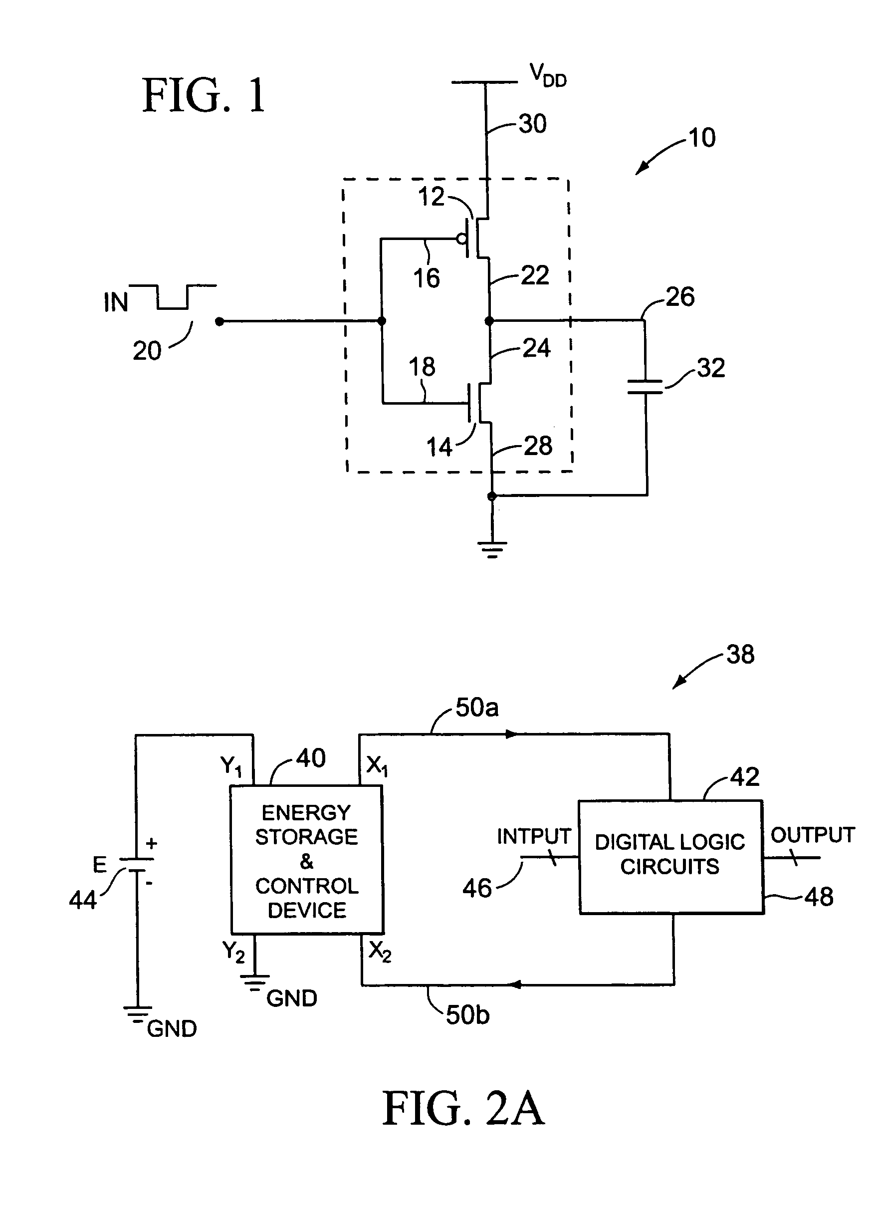
[0041]FIG. 2A shows a general block diagram of an apparatus 38, in accordance with the present invention. The apparatus 38 of FIG. 2A includes an energy storage and control device 40 and digital logic circuitry 42 having at least one input 46 and at least one output 48. In general terms, the energy storage device and control device 40 is a two-port device, one port Y1–Y2 being connected to a main power source 44 and the other port X1–X2 being connected to the supply and return lines of the digital logic circuitry 42. The energy storage and control device 40 has two important functions. First, the energy storage and control device 40 provides operational energy to and recaptures operational energy from the digital logic circuitry 42. Second, it acts as a conduit to transfer energy from the main power supply 44 Y1–Y2 port to the digital logic circuitry 42 port X1–X2 to make up for the actual energy lost due to heat dissipation in the digital logic circuitry. Thus, the total amount of ...


PUM


Abstract

A method and apparatus for operating logic circuitry with recycled energy. Logic circuitry is used which has a node for storing energy and a return node that is connected to energy storage circuitry. The logic circuitry operates, using energy stored on the node, to determine a logic output based on a logic input during a first phase. The energy storage circuitry capture a portion of the stored energy during the operation of the logic circuitry and transfers a portion of the captured energy back to the node during a second phase. The energy storage circuitry oscillates with a determinable period and is tunable so that its oscillations can be synchronized to a clock.

Description

CROSS REFERENCE TO RELATED APPLICATIONS[0001]This application is a continuation of a regular U.S. Application, titled “RESONANT LOGIC AND THE IMPLEMENTATION OF LOW POWER DIGITAL INTEGRATED CIRCUITS”, Ser. No. 10 / 388,841, filed on Mar. 14, 2003 is now a U.S. Pat. No. 6,812,748, which is a continuation of a regular U.S. Application, titled “RESONANT LOGIC AND THE IMPLEMENTATION OF LOW POWER DIGITAL INTEGRATED CIRCUITS”, Ser. No. 09 / 967,189, filed on Sep. 27, 2001, now U.S. Pat. No. 6,559,681, which is a continuation-in-part of regular U.S. Application, titled “RESONANT LOGIC AND THE IMPLEMENTATION OF LOW POWER DIGITAL INTEGRATED CIRCUITS”, Ser. No. 09 / 614,494, filed on Jul. 11, 2000, now U.S. Pat. No. 6,448,816.BACKGROUND OF THE INVENTION[0002]1. Field of the Invention[0003]The present invention generally relates to reduced power operation of digital circuitry and more specifically to a method and apparatus for operating logic circuitry with alternating power phases.[0004]2. Descripti...

Claims


Application Information

Patent Timeline
Patent Type & Authority Patents(United States)
IPC IPC(8): H03K19/096H02M3/07H03K17/06
CPCH02M3/073H03K19/0963H03K17/063
Inventor WU, JIANBINGUO, WEIWEIYAO, YUAN
Owner PICONETICS INTPROP TRUST
Why Eureka
Try Eureka