Method and apparatus for detecting, locating, and identifying microwave transmitters and receivers at distant locations

Active Publication Date: 2006-11-28
THE BOEING CO
View PDF7 Cites 56 Cited by
  • Summary
  • Abstract
  • Description
  • Claims
  • Application Information

AI Technical Summary

Problems solved by technology

In the far field the beams interfere with microwave devices that will reradiate under carefully controlled conditions of the illuminating fields.
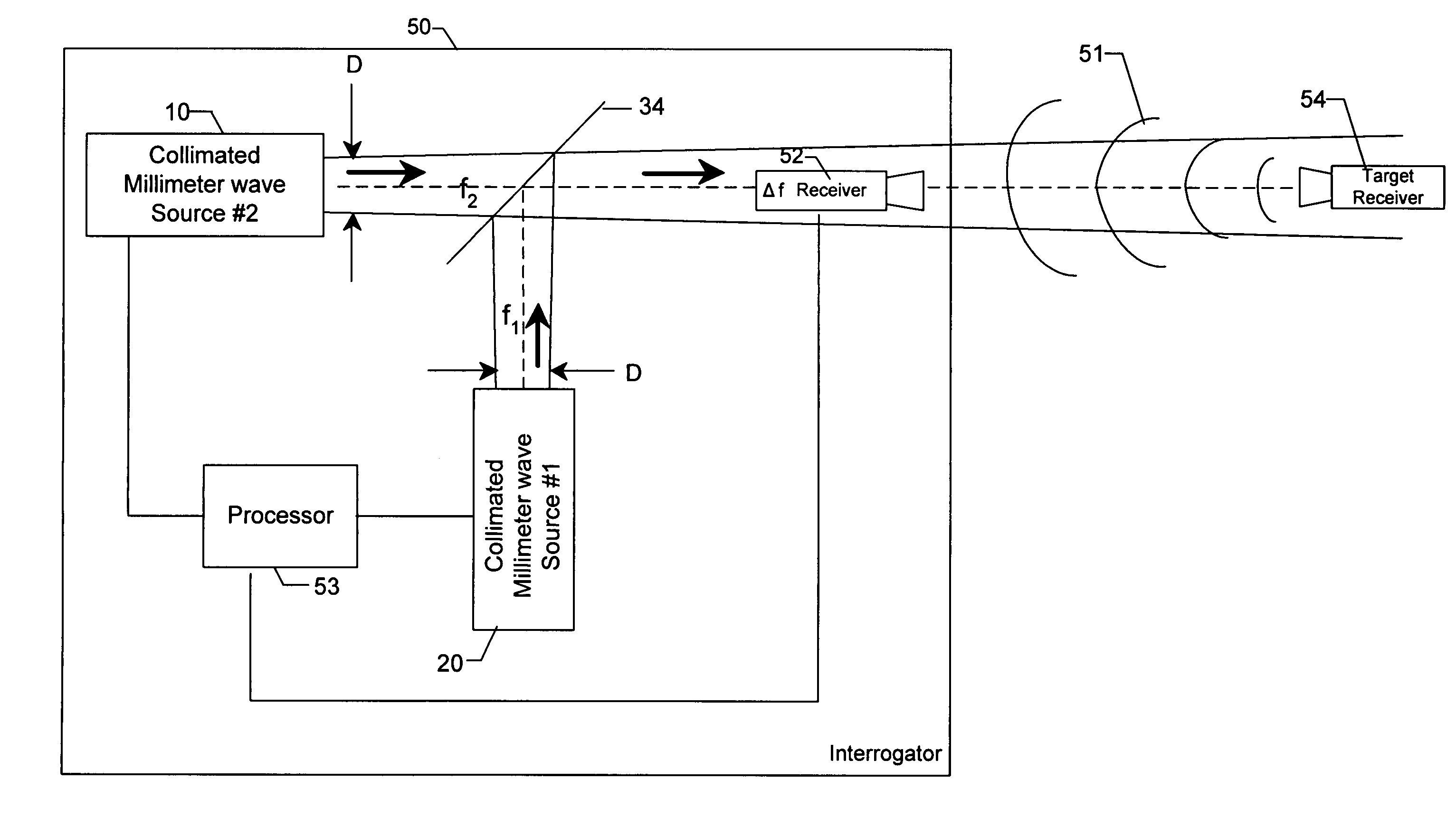
Also, the first and second transmitters are configured such that the first and second beams interfere with a target microwave device at a far field distance.

Method used


Image

  • Method and apparatus for detecting, locating, and identifying microwave transmitters and receivers at distant locations
  • Method and apparatus for detecting, locating, and identifying microwave transmitters and receivers at distant locations
  • Method and apparatus for detecting, locating, and identifying microwave transmitters and receivers at distant locations

Examples


Embodiment Construction

[0021]The present inventions now will be described more fully hereinafter with reference to the accompanying drawings, in which some, but not all embodiments of the inventions are shown. Indeed, these inventions may be embodied in many different forms and should not be construed as limited to the embodiments set forth herein; rather, these embodiments are provided so that this disclosure will satisfy applicable legal requirements. Like numbers refer to like elements throughout.

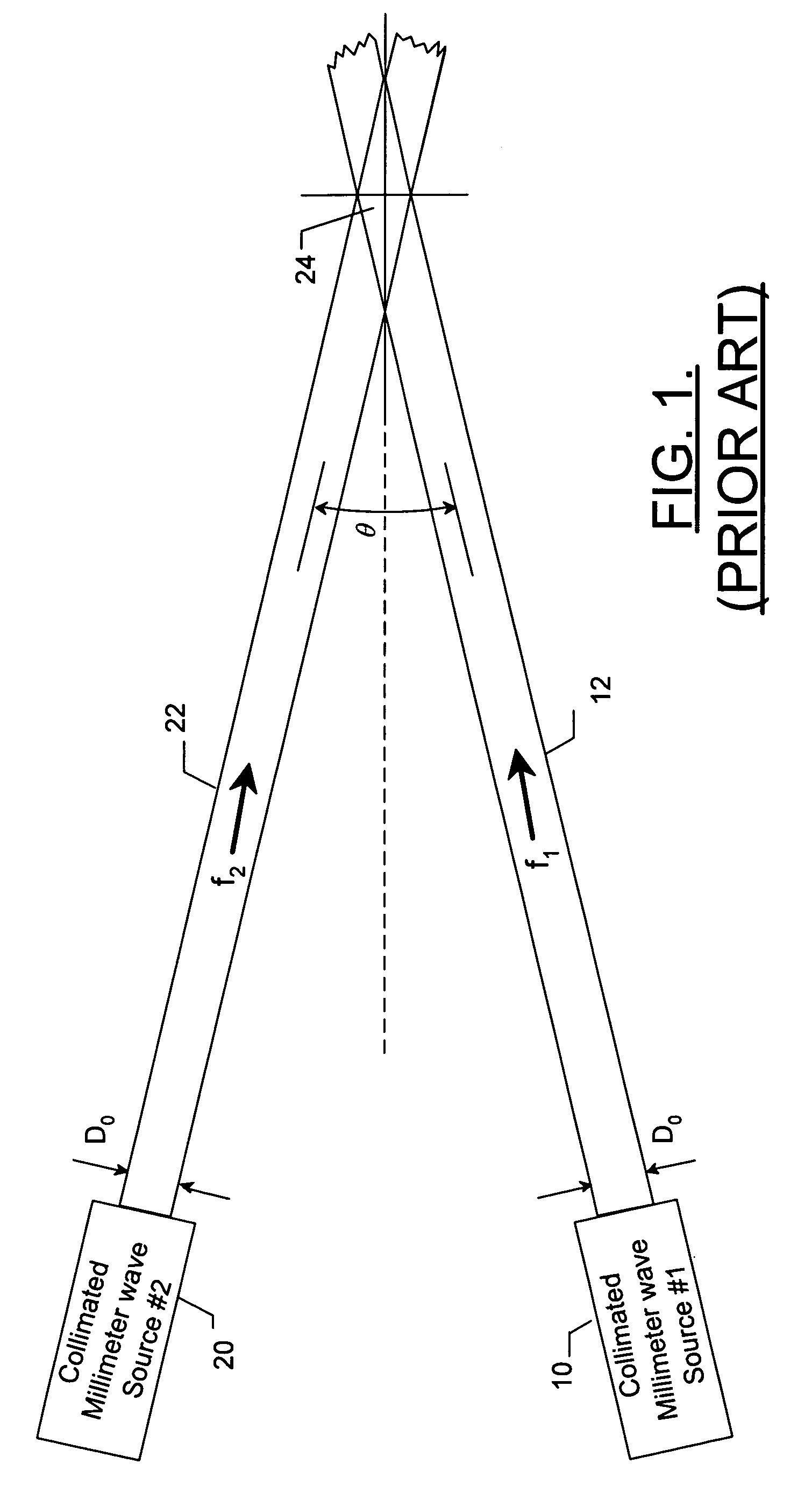
[0022]According to the method for detecting, locating, and identifying microwave transmitters and receivers at distant locations, collimated beams of electromagnetic radiation at two separate frequencies, f1 and f2, and in two intersecting directions, converge at a distance to form an interference zone. The interference zone, in turn, will be directed toward a target at a distance. A target has electronic components comprising one or more conductors, such as those that comprise a microwave transmitter and rece...


PUM


Abstract

Methods and apparatuses for detecting, locating, and identifying microwave transmitters and receivers at distant locations are disclosed. First and second electromagnetic beams at first and second frequencies, respectively, are transmitted in first and second directions. The second frequency is offset from the first frequency to define an interference difference frequency. As such, the first and second electromagnetic beams interfere at a far field distance corresponding to an intersection of the first and second electromagnetic beams. In the far field the beams interfere with microwave devices that reradiate a return radiation at the difference frequency. The methods and apparatuses detect the return radiation at the difference frequency, such as by way of a receiver, and locate the interference zone to determine the location of the microwave device, such as by a processor.

Description

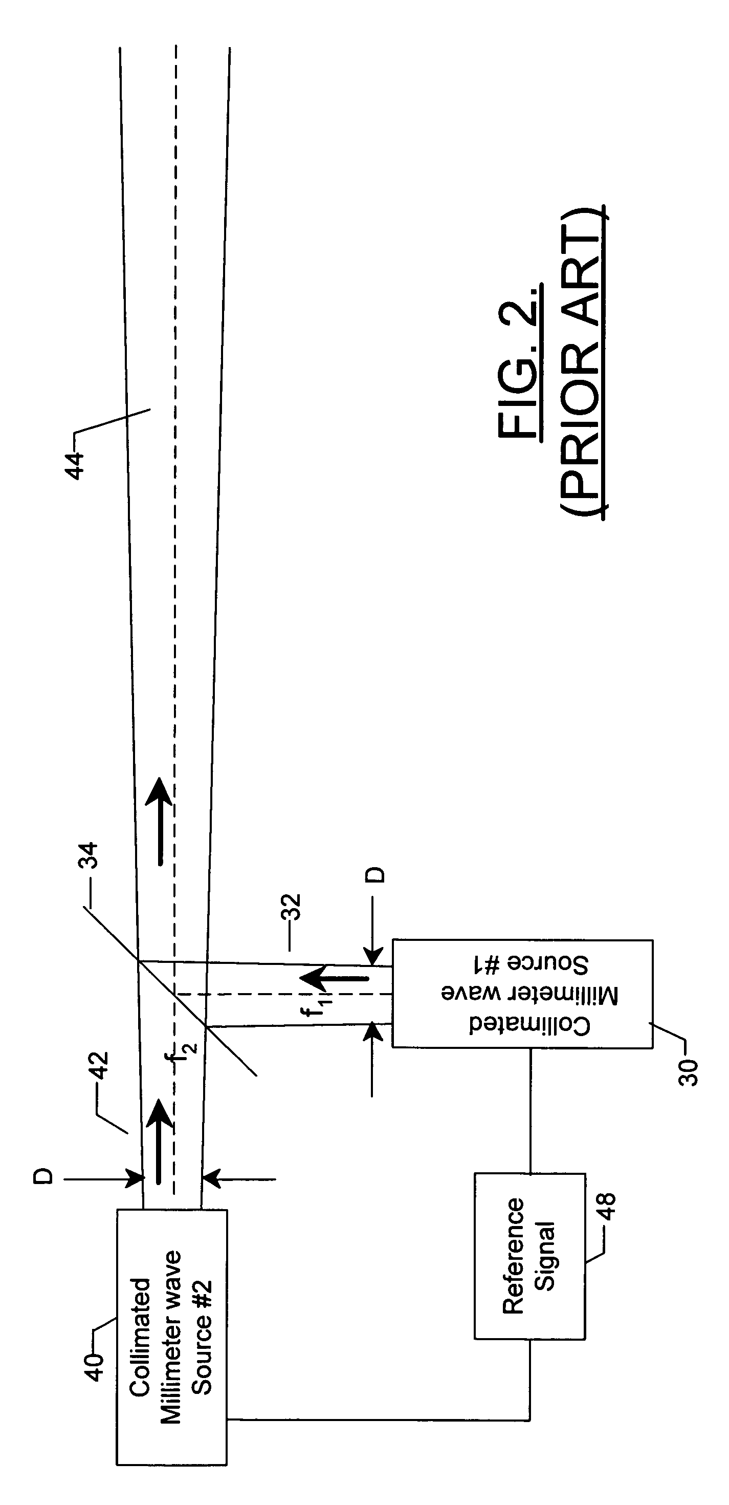
FIELD OF THE INVENTION[0001]The present invention relates to methods and apparatuses for detecting, locating, and identifying microwave transmitters and receivers at distant locations, and, more particularly, to a method and apparatus for identifying microwave transmitters and receivers at distant locations using controlled and directed electromagnetic energy.BACKGROUND OF THE INVENTION[0002]As described in co-pending U.S. patent application Ser. No. 10 / 444,510, FIG. 1 illustrates two millimeter wave sources 10, 20 radiating collimated beams 12, 22 of electromagnetic radiation at two separate frequencies, f1 and f2, and in two intersecting directions that overlap at a distance. See U.S. patent application Ser. No. 10 / 444,510, entitled: Method And Apparatus For Directing Electromagnetic Radiation To Distant Locations, filed May 23, 2003, the contents of which are hereby incorporated by reference in its entirety. Generally, when two electromagnetic beams of different frequencies conve...

Claims


Application Information

Patent Timeline
Patent Type & Authority Patents(United States)
IPC IPC(8): G01S7/38G01S7/02G01S13/04G01S13/42G01S13/46G01S13/74G01V8/00
CPCG01S7/021G01S13/04G01S13/74G01V8/005G01S13/42G01S13/46G01S13/003G01S13/48G01V3/12H04K3/00
Inventor HOLLY, SANDOR
Owner THE BOEING CO
Why Eureka
Try Eureka