Servo writer and servo writing process

a technology of servo writing and servo, applied in the field of servo writer and servo writing process, can solve the problem of inability to perform high-precision position control

Inactive Publication Date: 2006-11-28
FUJIFILM HLDG CORP +1
View PDF7 Cites 53 Cited by
  • Summary
  • Abstract
  • Description
  • Claims
  • Application Information

AI Technical Summary

Problems solved by technology

As a result, the recording / playing device of the magnetic tape cannot read the servo signal SS in a precise manner, and highly precise control of the position cannot be performed.

Method used


Image

  • Servo writer and servo writing process
  • Servo writer and servo writing process
  • Servo writer and servo writing process

Examples


first embodiment

[First Embodiment]

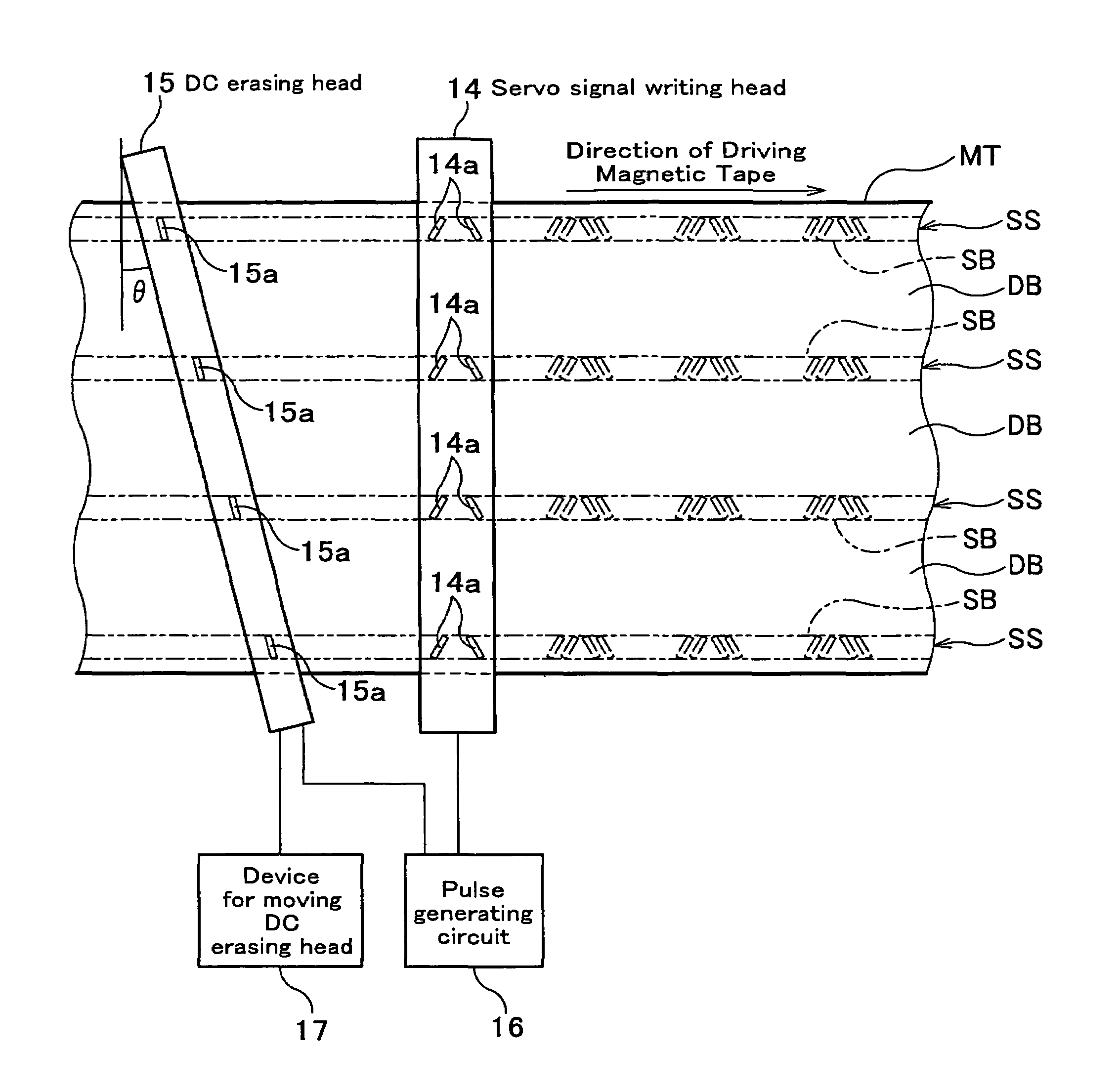
[0026]The first embodiment of the servo writer according to the present invention will now be described by referring to the attached drawings. The servo writer according to the present invention is characterized in that an azimuth of a DC erasing head contained in the servo writer is adjustable. The term “azimuth relative to the servo band” used herein means an angle of magnetic gap of the magnetic head relative to the orthogonal direction of the servo band.

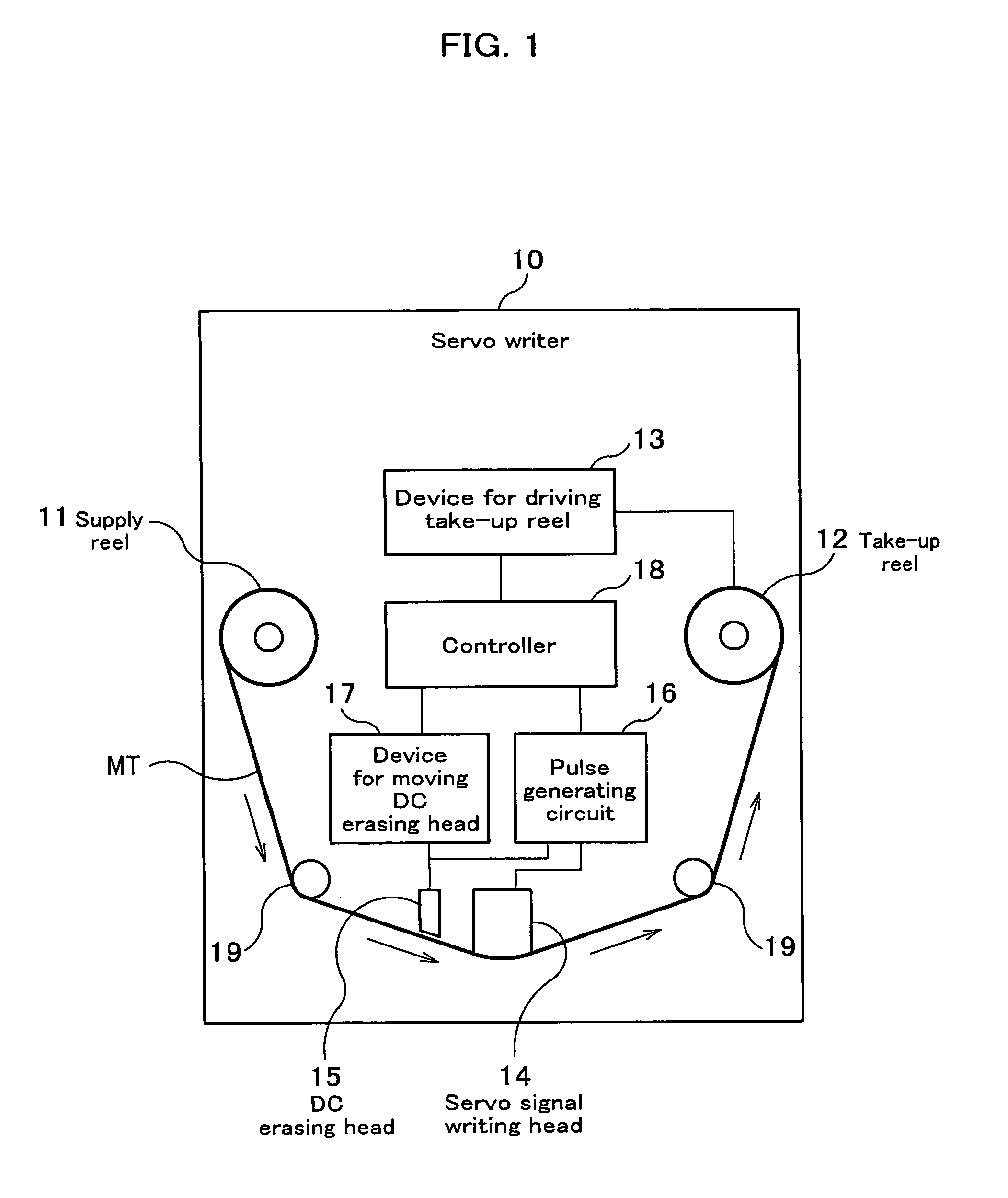
[0027]The construction of the servo writer according to the present invention will now be described. It is noted that the servo writer is a device which is used in a stage for writing a servo signal onto a magnetic tape.

[0028]A servo writer 10 shown in FIG. 10 mainly comprises a supply reel 11, a take-up reel 12, a device 13 for driving take-up reel, a servo signal writing head 14, a DC erasing head 15, a pulse generating circuit 16, a device 17 for moving DC erasing head, a controller 18, and a plurality of gui...

second embodiment

[Second Embodiment]

[0047]Second embodiment of the servo writer according to the present invention will now be described. Since this embodiment modifies the servo writer according to the first embodiment, the constitution elements similar to those of the first embodiment are assigned to the same numerical or symbols, the description thereof will be omitted.

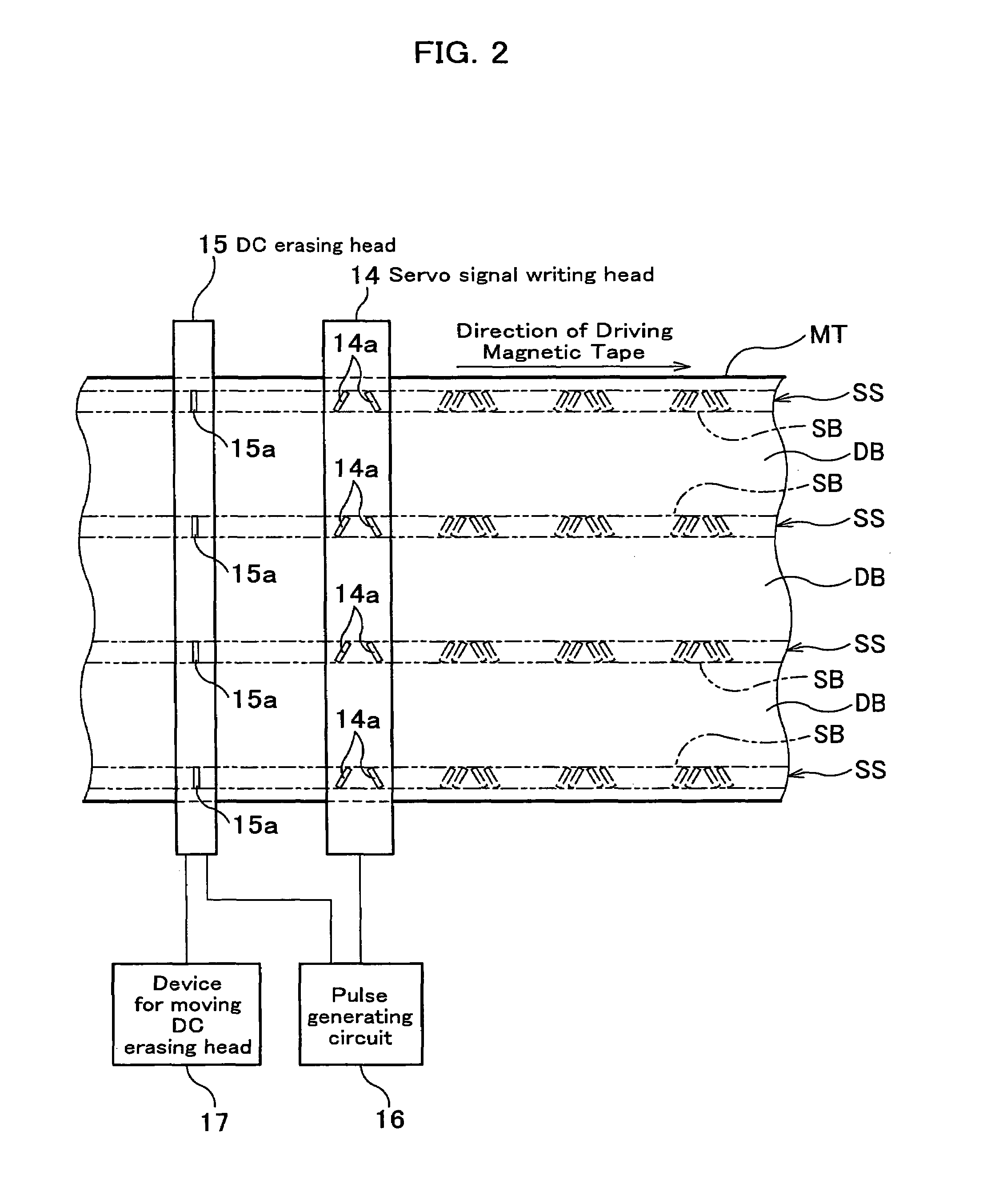
[0048]As shown in FIG. 6, head gaps 15b are formed on the DC erasing head so that they project prescribed length on both ends of the magnetic tape MT in the width direction in order to cover the whole of the magnetic tape MT in the width direction. Specifically, the head gaps 15b are formed into a length so as to cover each of the servo bands SB even if the DC erasing head 15 is rotated up to the maximum azimuth, which has been predetermined.

[0049]Between the DC erasing head 15 and the servo signal writing head 14, an AC erasing head 20, which AC magnetizes the data band DB positioned between the servo bands SB (magnetization at ra...


PUM

PropertyMeasurementUnit
currentaaaaaaaaaa
magneticaaaaaaaaaa
magnetizing forceaaaaaaaaaa

Abstract

A servo writer according to the present invention is a servo writer which writes a servo signal on a servo band of a magnetic tape. It comprises a magnetic tape driving system in which a magnetic tape supplied from a supply reel is taken up by a take-up reel to drive the magnetic tape; a DC erasing head which is slidably in contact with said driving tape and which DC-magnetizes said servo band with imparting an azimuth relative to said servo band; and a servo signal writing head provided on a downstream of said DC erasing head in the driving direction of the magnetic tape, which is slidably in contact with said driving tape and which magnetizes the servo band by a magnetizing force having a component with a reverse magnetizing force relative to the magnetizing force of the DC erasing head in the lengthwise direction of the magnetic tape.

Description

BACKGROUND ARTS[0001]1. Field of the Invention[0002]The present invention relates to a servo writer and a servo writing process, and particularly to a servo writer and a servo writing process, which can magnetize a servo band of a magnetic tape depending upon the degree of the thickness of a magnetic layer, disclosure of which is based on Japanese Patent Application Number 2003-296343, filed on Aug. 20, 2003, which is incorporated herein by reference.[0003]2. Description of Related Arts[0004]In recent years, a magnetic recording medium has increasingly be able to recorded at higher density, for example, there exists a recording medium for backing up data for computer has a capacity as high as 100 Gigabytes. For this reason, several hundreds of data tracks are formed in a width direction in the magnetic tape. In this connect, the width of the data track becomes very narrow accordingly, and a space between neighboring data tracks also becomes very narrow. For this reason, a technique ...

Claims


Application Information

Patent Timeline
Patent Type & Authority Patents(United States)
IPC IPC(8): G11B5/584G11B5/02G11B5/03C09K11/08H05B33/14C23C14/08C23C14/34G11B5/008G11B5/024G11B5/48H05B33/10
CPCG11B5/584G11B5/00813G11B5/024G11B5/4893C09K11/08C23C14/08C23C14/3414Y10S428/917
Inventor TATEISHI, SEIJINAKAO, TORU
Owner FUJIFILM HLDG CORP
Why Eureka
Try Eureka