System and method for improving communication between a switched network and a packet network

a packet network and switched network technology, applied in the field of telecoms, can solve the problems of difficult routing of calls, further management issues, complicated management issues, etc., and achieve the effect of improving communication

Active Publication Date: 2006-11-28
SILICON VALLEY BANK
View PDF5 Cites 50 Cited by
  • Summary
  • Abstract
  • Description
  • Claims
  • Application Information

AI Technical Summary

Benefits of technology

[0013]In light of the foregoing, the present invention generally relates to systems and methods for improving communication between a switched network and a packet network.

Problems solved by technology

Unfortunately, when running a network that comprises many softswitches, the owner of the network has many different points of policy management that need to be maintained to create a full mesh.
Such policy management issues include assuring that each softswitch knows the IP address of each other softswitch and what telephone numbers or PSTN to which they connect.
When running softswitches from multiple vendors, further management issues arise.
The management issues are then more complicated due to the fact that the equipment may be managed through different interfaces.
In the full mesh routing arrangement, the routing of calls may be difficult since several different egress softswitches may be full or not functioning.
This search effort can be greatly reduced if a purely random distribution is implemented, however, it is assumed that some routes would be preferred over others due to cost or quality, thereby exacerbating the problem.
In addition, the excessive functionality of softswitches, as is demonstrated by, for example, the excessive use of state sharing, causes a decrease in the flow of information (data and / or voice).

Method used


Image

  • System and method for improving communication between a switched network and a packet network
  • System and method for improving communication between a switched network and a packet network
  • System and method for improving communication between a switched network and a packet network

Examples


Embodiment Construction

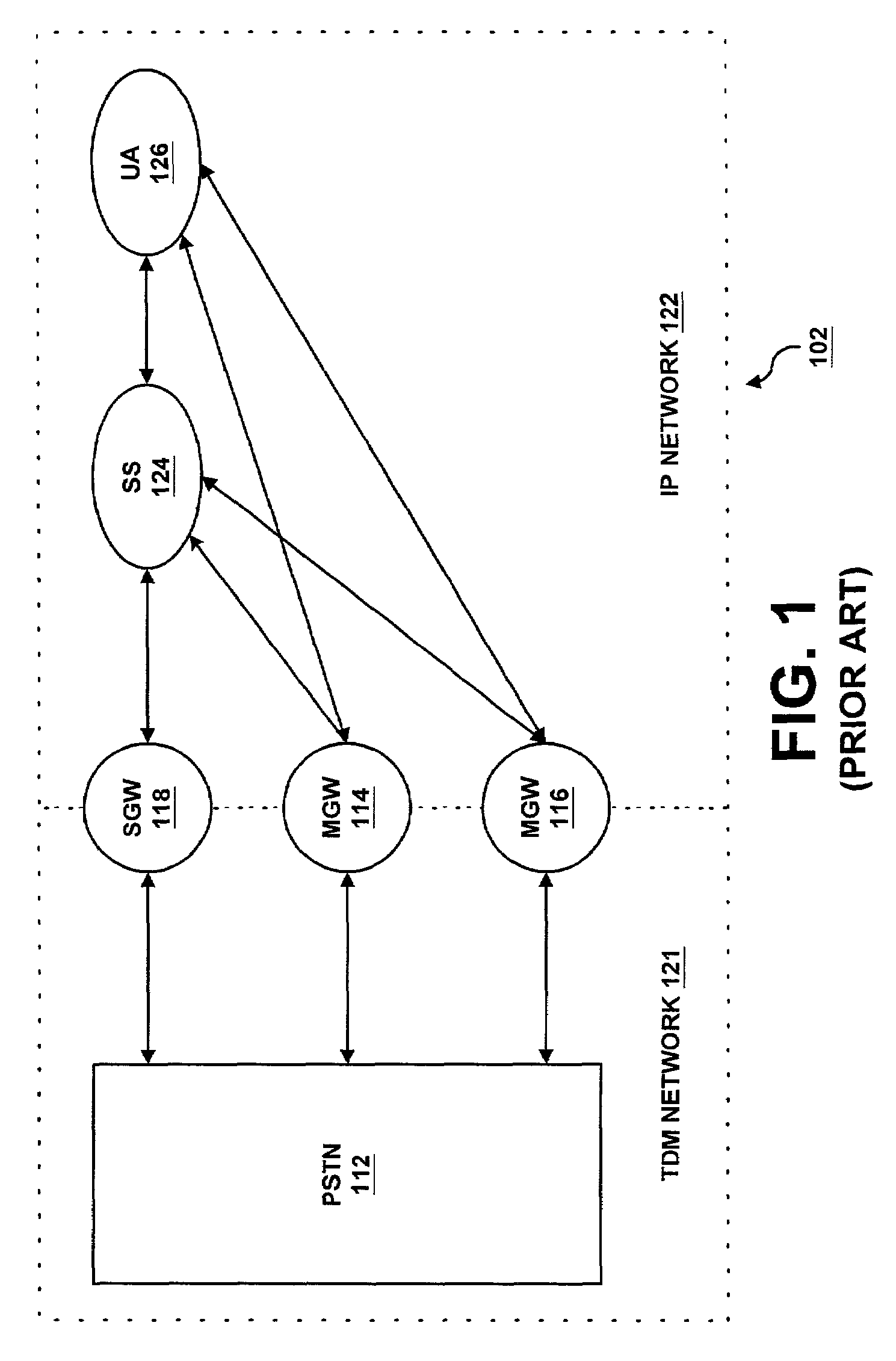
[0036]Referring now to the drawings, wherein like reference numerals designate corresponding parts throughout the drawings, FIG. 1 is a block diagram illustrating a prior art communication network 102. As is shown by FIG. 1, the prior art communication network 102 comprises a PSTN 112, located within a time division multiplexing (TDM) network 121, that is in communication with a user agent 126 located within an IP network 122, as is further described hereinbelow. It should be noted that the IP network 122 may instead be any packet data network. The PSTN 112 segments signaling data and voice on the network 102, thereby allowing for performance guarantees of different traffic components to be set independently.

[0037]To allow a call made on a traditional circuit to be recast in IP packets, and vice versa, a first and second media gateway 114, 116 are utilized by the prior art communication network 102. It should be noted that the number of media gateways may be less or more in accordan...


PUM


Abstract

A system and method for improving communication between a switched network and a packet network is disclosed. In a simplified embodiment, a signaling gateway is utilized for converting signaling in a first protocol into a second protocol, and from the second protocol to said first protocol. At least one media gateway is utilized for converting multimedia provided in a first format into a second format, and from the second format into the first format. A session router for selecting at least one multimedia transmission route to a destination is also utilized, wherein the destination is specified by the switched network. In addition, a media router is also utilized for guiding the multimedia to the destination after conversion by the media gateway.

Description

CROSS-REFERENCE TO RELATED APPLICATIONS[0001]This application is a continuation-in-part of U.S. patent application entitled, “System and Method for Determining Flow Quality Statistics for Real-Time Transport Protocol Data Flows,” filed on Jul. 23, 2001, and having Ser. No. 09 / 911,256; U.S. Application entitled, “System and Method for Providing Rapid Rerouting of Real-Time Multimedia Flows,” filed on Jul. 23, 2001, and having Ser. No. 09 / 911,304; and U.S. patent application entitled, “System and Method for Providing Encryption for Rerouting of Real-Time Multimedia Flows,” filed on Aug. 28, 2001, and having Ser. No. 09 / 941,229, all of the foregoing disclosures of which are incorporated by reference herein in their entirety.FIELD OF THE INVENTION[0002]The present invention generally relates to telecommunications and, more particularly, is related to a system and method for improving communication between a switched network and a packet network.BACKGROUND OF THE INVENTION[0003]The publi...

Claims


Application Information

Patent Timeline
Patent Type & Authority Patents(United States)
IPC IPC(8): H04L12/66H04L12/64H04L45/42H04M7/00H04M7/12
CPCH04L12/6418H04L12/66H04L29/06027H04L45/00H04L45/42H04M7/1225H04M7/1285H04L65/1043H04L65/605H04L65/1006H04L65/608H04L67/14H04L69/08H04L69/18H04L2012/6472H04L2012/6475H04L2012/6486H04L65/765H04L65/1104H04L65/65H04L65/1101
Inventor PENFIELD, ROBERT F.MELAMPY, PATRICK J.COMMERFORD, PETER S.
Owner SILICON VALLEY BANK
Why Eureka
Try Eureka