Sewing machine with automatic needle threader

a needle threading machine and needle thread technology, which is applied in the direction of sewing machine control devices, sewing apparatus, textiles and paper, etc., can solve the problems of damage to the threading member and difficulty in improving the efficiency of the needle threading process, and achieve the effect of avoiding interference between the threading hook and the pressing foo

Active Publication Date: 2006-12-05
BROTHER KOGYO KK
View PDF8 Cites 6 Cited by
  • Summary
  • Abstract
  • Description
  • Claims
  • Application Information

AI Technical Summary

Benefits of technology

[0009]Therefore, an object of the present invention is to provide a sewing machine, which is capable of automatically performing the entire needle threading process by a threading mechanism independent of the location of a presser bar.
[0010]The present invention provides a sewing machine comprising a needle bar holding a sewing needle having a thread eye, a needle threading mechanism including a threading hook passing a needle thread through the thread eye of the sewing needle, a presser bar having a lower end to which a presser foot is attached, a vertically moving mechanism vertically moving the presser bar, a drive mechanism driving the vertically moving mechanism, a needle threading operation unit operating the needle threading mechanism, and a drive mechanism controlling unit controlling the drive mechanism vertically moving the presser bar to a position where interference between the presser foot and the threading hook is avoided when the needle threading operation unit is operated.
[0011]The invention also provides a sewing machine comprising a needle bar holding a sewing needle having an eye hole, a thread retaining member retaining the needle thread, a thread transferring mechanism constructed to move the thread retaining member near the eye hole of the sewing needle thereby to transfer the needle thread near the eye hole, a presser bar with a presser foot attached to a lower end thereof, a vertically moving mechanism vertically moving the presser bar, a drive mechanism driving the vertically moving mechanism, a thread transferring operation unit operating the thread transferring mechanism, and a drive mechanism controlling unit controlling the drive mechanism so that the presser bar is vertically moved to a position where interference between the presser foot and the thread retaining member is avoided when the thread transferring operation unit has been operated.
[0012]According to the above construction, by the user's operation of the threading operation unit, the needle threading process is automatically performed with presser bar vertically moved to the position to avoid the interference between the presser foot and thread retaining member. This enables the entire needle threading process to be performed automatically, not requiring any work on the part of the user.

Problems solved by technology

When an automatic threading mechanism is activated in the state, in which the presser bar is in the elevated position, a threading hook member of the automatic threading mechanism and the presser foot interferes with each other and the threading member may be damaged.
That is, even in the case of performing needle threading by the automatic threading mechanism, manual operation needs to be performed and it becomes difficult to improve an efficiency of the needle threading process.

Method used


Image

  • Sewing machine with automatic needle threader
  • Sewing machine with automatic needle threader
  • Sewing machine with automatic needle threader

Examples


Embodiment Construction

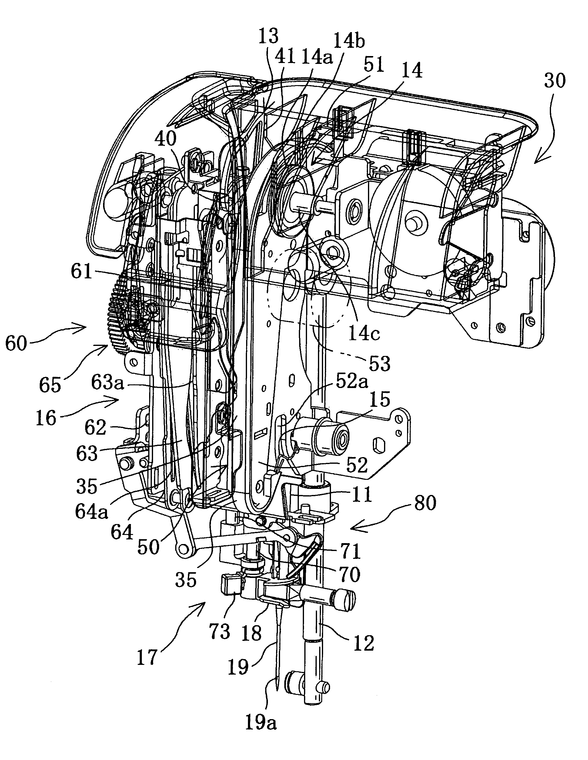
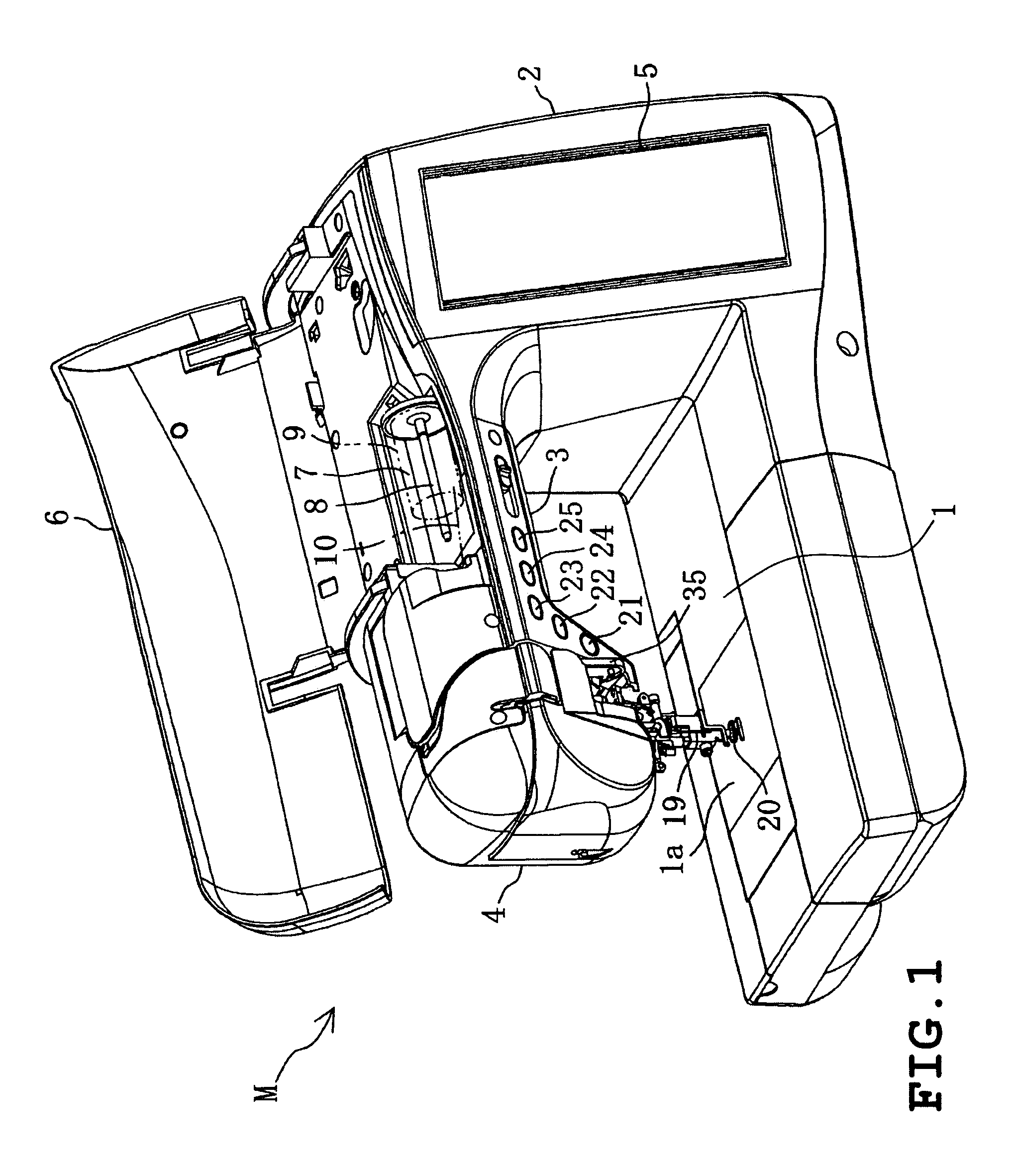
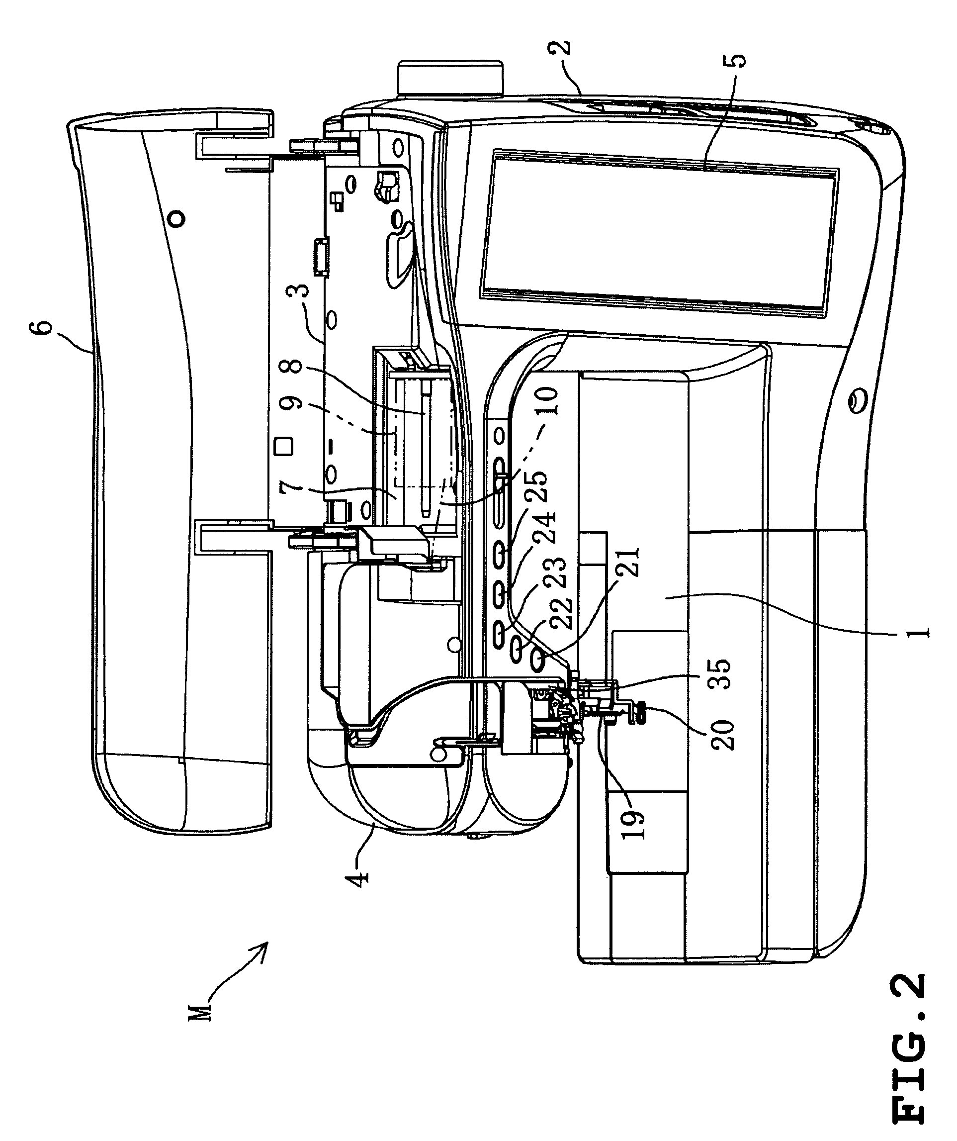
[0040]The embodiments of the present invention is explained with reference to the drawings hereinafter. As shown in FIGS. 1–3, a sewing machine M has a sewing bed 1, a sewing pillar 2 provided in the right side of the bed 1, a sewing arm 3 extending from an upper part of the foot to the left converging the bed 1 and a sewing head 4 provided on the left side of the arm 3. The bed 1 is provided with a needle plate 1a and among the bed 1 parts, a rotary hook mechanism (not shown) is provided under the needle plate 1a. A bobbin on which a bobbin thread is wound is detachably attached to a rotary hook mechanism. On the front surface of the pillar 2, a liquid crystal display 5 is provided. On the front surface of the lower part arm 3, a sewing start switch 21, a sewing end switch 22, an automatic thread hook preparation switch 23, a presser foot moving switch 24, an automatic thread hook start switch 25 (corresponding to a thread operation unit) are provided.

[0041]An openable cover 6 is a...


PUM


Abstract

A sewing machine includes a needle bar holding a sewing needle having an eye hole, a needle threading mechanism including a threading hook passing a needle thread through the eye hole of the sewing needle, a presser bar with a presser foot attached to its lower end, a vertically moving mechanism vertically moving the presser bar, a drive mechanism driving the vertically moving mechanism, a threading operation unit operating the needle threading mechanism, and a drive mechanism controlling unit controlling the drive mechanism vertically moving the presser bar to a position where interference between the presser foot and threading hook is avoided when the needle threading operation unit is operated.

Description

BACKGROUND OF THE INVENTION[0001]1. Filed of the Invention[0002]The present invention relates to a sewing machine having a needle threading mechanism, which automatically threads a thread eye of a sewing needle.[0003]2. Description of the Related Art[0004]Conventional sewing machines have a plurality of thread passing parts (a thread tension regulator, a thread take-up spring, a thread take-up lever, a needle bar thread guide etc.), through which a needle thread extending from a thread spool is passed. After having been passed through the thread passing parts in a predetermined sequence and path, the needle thread is passed through a thread eye of a sewing needle attached to a needle bar. Also, some of the conventional sewing machines have an automatic needle threader having a thread retaining member and a threading member to retain the end of the needle thread in order to automatically pass the needle thread through the needle eye of the sewing needle. In the above sewing machine, ...

Claims


Application Information

Patent Timeline
Patent Type & Authority Patents(United States)
IPC IPC(8): D05B87/02D05B19/12D05B69/00
CPCD05B19/12D05B69/00D05B87/02
Inventor FUJIHARA, SHINYAMIZUNO, NOBORUSHOJI, YOSHIHISA
Owner BROTHER KOGYO KK
Why Eureka
Try Eureka