Valve element

a valve element and valve body technology, applied in the field of valve elements, can solve the problems of not producing the desired size of the hole, blocking the flow of pressure medium,

Inactive Publication Date: 2006-12-05
MARIOFF CORP OY
View PDF16 Cites 20 Cited by
  • Summary
  • Abstract
  • Description
  • Claims
  • Application Information

AI Technical Summary

Benefits of technology

[0006]The solution of the invention has numerous significant advantages. The passage through the piston ensures that the piston will be effectively pressed towards the burst disk after the disk has been pierced even in cases where a higher pressure prevails on the opposite side of the burst disk than on the side of the piston-piercer combination. The solution of the invention is leak-proof and reliable. By making the channel formed through the piston element a part of the passage for the pressure medium, a passage having a constant diameter in all circumstances is achieved.BRIEF DESCRIPTION OF THE FIGURES

Problems solved by technology

A device corresponding to the subject of the invention is known from specification DE 2635076 A. One of the drawbacks of this solution is that the piercing element is returned by the action of pressure back to its original position, so a piece of the burst disk that may have been detached from it by the piercing action may partially block the passage and thus form an obstacle to the flow of pressure medium.
If the piercing movement is for some reason incompletely executed, it will not produce a hole of the desired size.

Method used


Image

  • Valve element
  • Valve element
  • Valve element

Examples


Embodiment Construction

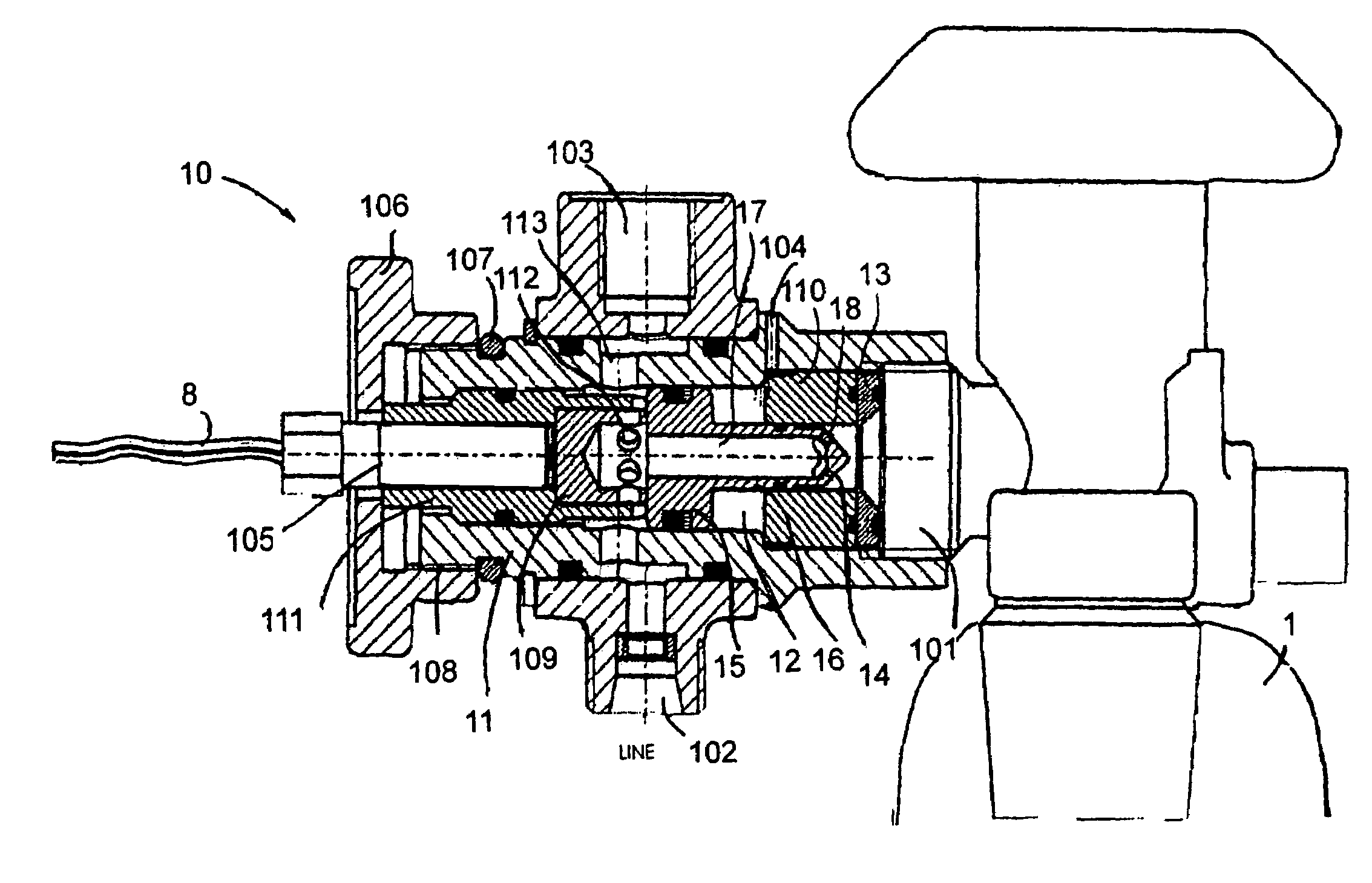
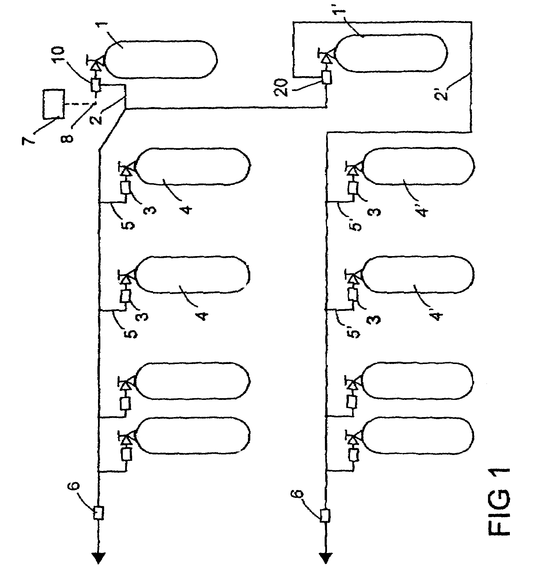
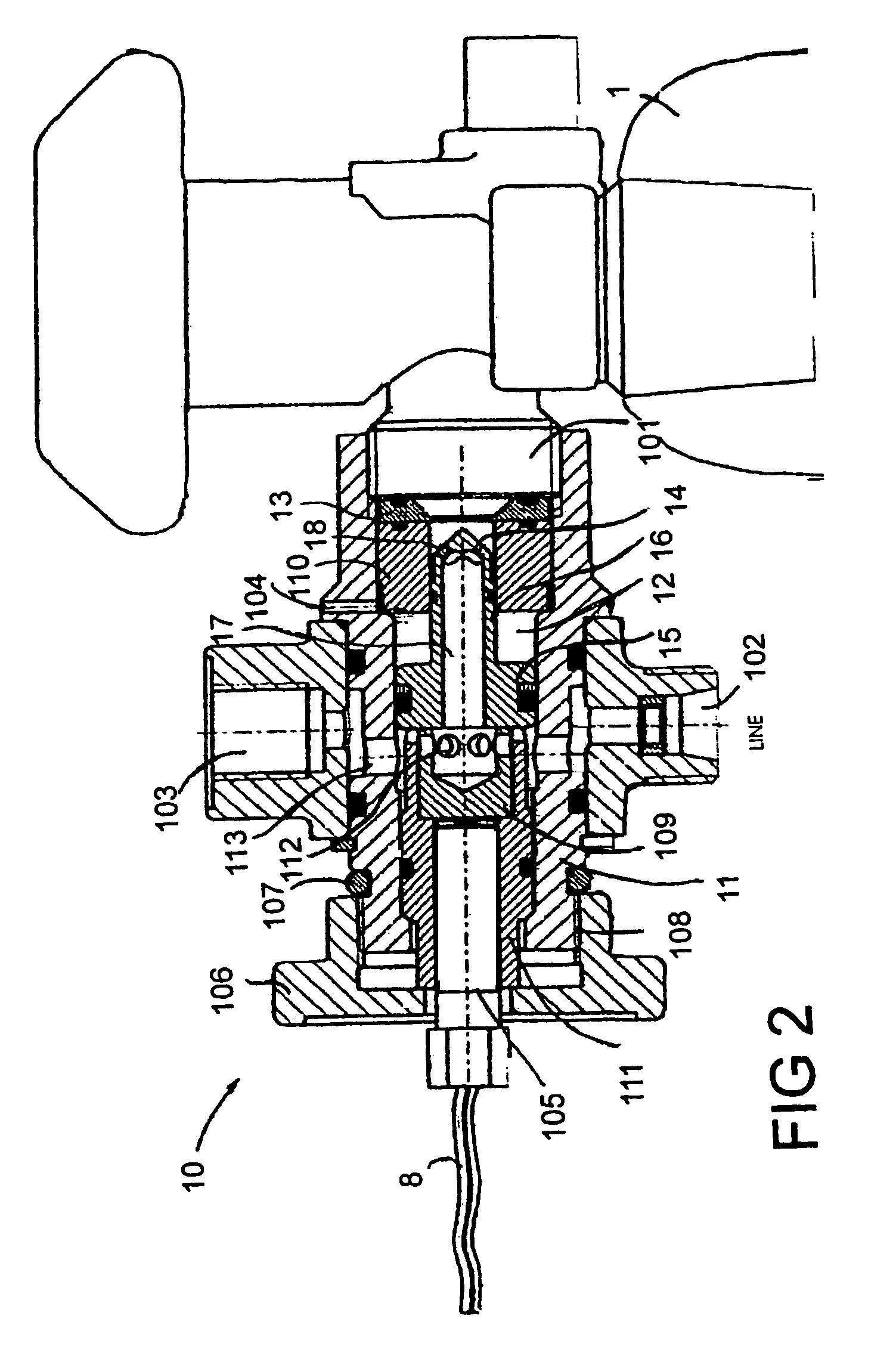
[0012]FIG. 1 is a diagrammatic representation of a pressure system in which it is possible to utilize valve elements according to the invention. The system comprises at least two parallel-connected pressure sources 4, 4′, which in the solution represented by the figure consist of four pressure containers 4, 4′ each. In addition, the system comprises at least one first pressure source 1 and means for opening a connecting passage from the first pressure source 1 to a pressure network 2, which communicates with a first pressure source 4. The means for opening a connecting passage comprise a first valve element 10, which is disposed between the first pressure source 1 and the pressure network 2. When the first valve element 10 is opened, e.g. triggered by a control system 7 or manually, the pressure in the network 2 rises. This has the effect of opening second valve elements 3, which are disposed at least in the passage 5 between the first pressure source 4 and the network 2. After the ...


PUM


Abstract

Valve element (3, 6, 10), comprising a frame, at least one inlet and at least one outlet, a passage connecting the inlet and outlet, at least one burst disk (13, 35, 63) or equivalent, which, when unbroken, closes the passage from inlet to outlet, and a piston element (15, 36, 65) provided with a piercing element or the like for piercing the burst disk. The piston element (15, 36, 65) is provided with a passage (17, 39, 67) for a pressure medium, said passage extending axially through the piston element from one first side to one second side, which passage leading through the piston forms a part of the passage of the pressure medium after the burst disk (13, 35, 63) has been pierced.

Description

BACKGROUND OF THE INVENTION[0001]The present invention relates to a valve element as defined in the preamble of claim 1, which comprises a frame, at least one inlet and at least one outlet, a passage connecting the inlet and outlet and at least one burst disk (rupture disk) or equivalent, which, when unbroken, closes the passage from inlet to outlet, and a piston element provided with a piercing element or the like for piercing the burst disk.[0002]A device corresponding to the subject of the invention is known from specification DE 2635076 A. One of the drawbacks of this solution is that the piercing element is returned by the action of pressure back to its original position, so a piece of the burst disk that may have been detached from it by the piercing action may partially block the passage and thus form an obstacle to the flow of pressure medium. In addition, the piercing element has to go completely through the burst disk in order to produce a hole of the desired size in the d...

Claims


Application Information

Patent Timeline
Patent Type & Authority Patents(United States)
IPC IPC(8): F16K17/40A62C35/68A62C13/70A62C35/02A62C35/66F16K17/16
CPCA62C13/70A62C35/023A62C35/68F16K17/1626Y10T137/1647Y10T137/1767F16K17/04A62C35/02
Inventor SUNDHOLM, GORANMETZGER, HARRY
Owner MARIOFF CORP OY
Why Eureka
Try Eureka