Three-dimensional sipes for treads

a three-dimensional sipe and tread technology, applied in the field of pneumatic tires, can solve the problems of uneven tread, increased abrasion at the points, wear of the sipe, etc., and achieve the effect of improving the traction characteristics

Active Publication Date: 2006-12-05
THE GOODYEAR TIRE & RUBBER CO
View PDF25 Cites 38 Cited by
  • Summary
  • Abstract
  • Description
  • Claims
  • Application Information

AI Technical Summary

Benefits of technology

[0008]The present invention is directed to a tire tread having ground engaging elements having sipes therein. The sipe has a three dimensional portion formed from interlocking projections of alternating recesses and protrusions. The resulting constant interlocking aspect of the sipe prevents slippage of opposing faces of the sipe, reducing wear of the sipe faces. The effective length of the sipe is also increased by the planar bends in the sipe. The increased effective length reduces sudden decompression of the sipe as the tread element travels out of the tire footprint. This yields improved tread wear as the trailing edge of the tread element is not snapping out of the footprint.

Problems solved by technology

The easy relative longitudinal sliding between the opposed faces of the sipe weakens the resistance of the tread elements to flexing in the contact area between tread and road and therefor slows down the heat buildup of the tire; however, the sliding of the opposed faces of the sipes creates friction between the opposing sipe faces and can lead to wear of the sipes.
Due to the sharp lines forming the sipe configuration, while the opposing sides of the sipe interlock, there is increased abrasion at the points.
The rounded opposing edges of the sipe reduces rubbing but doesn't eliminate the movement of the opposing sipe faces.
The flat portions of the sipe are still subject to rubbing and wear.

Method used


Image

  • Three-dimensional sipes for treads
  • Three-dimensional sipes for treads
  • Three-dimensional sipes for treads

Examples


Embodiment Construction

[0035]The following language is of the best presently contemplated mode or modes of carrying out the invention. This description is made for the purpose of illustrating the general principles of the invention and should not be taken in a limiting sense. The scope of the invention is best determined by reference to the appended claims.

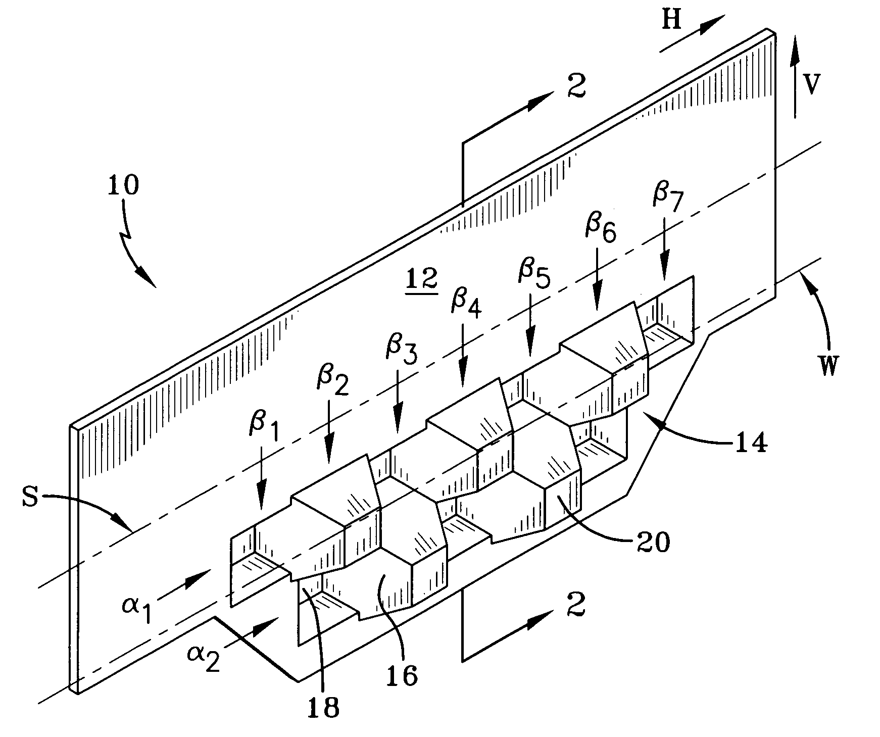
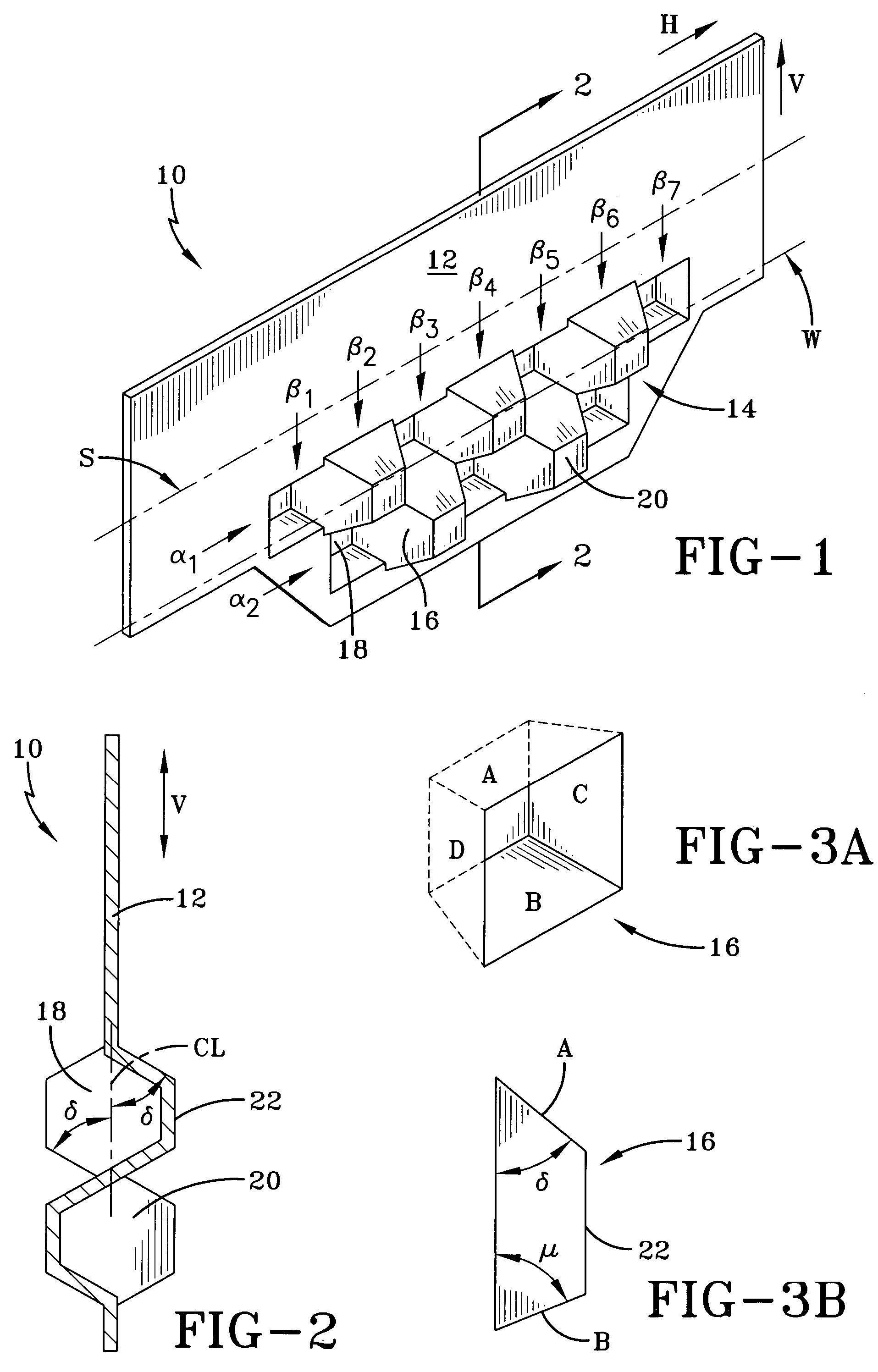
[0036]FIG. 1 illustrates a blade 10 in accordance with the present invention. The blade 10 has a planar portion 12 and a three-dimensional portion 14 comprising a plurality of adjacent projecting elements 16, seen on one side of the blade 10 as protrusions 18 and recesses 20, see FIG. 2. The blade 10 is made of metal, preferably steel, and the projecting elements 16 are made by stamping or embossing the steel sheet. Such a blade 10 is mounted into a tread mold such that the top planar portion 12 of the blade 10 is closer to the mold and the projections 16 are in the open space of the mold to form a three-dimensional portion in a sipe.

[0037]The three-dim...


PUM

PropertyMeasurementUnit
angleaaaaaaaaaa
thicknessaaaaaaaaaa
shapesaaaaaaaaaa

Abstract

Both a mold blade for forming sipes and the sipe so formed in a tire tread element have three dimensional portions. In the formed sipe, the three dimensional portion creates a constant interlocking of the opposing sipe faces. The blade and the sipe have at least one row of alternating polygonal shaped recesses and protrusions. The recesses and protrusions terminate in a vertex; the vertex has a planar, or two-dimensional, configuration that is parallel to either-the blade centerline or the sipe centerline.

Description

FIELD OF THE INVENTION[0001]The present invention is directed to a pneumatic tire. More specifically, the present invention is directed to the tread of a tire and the sipes in the tire tread.BACKGROUND OF THE INVENTION[0002]The tread portion of a pneumatic tire generally comprises a plurality of circumferentially and laterally extending grooves defining ground engaging rubber elements, the elements being in the form of blocks or ribs or combinations thereof. The particular size and shape of the tread elements contribute significantly to the overall performance of the tire and are for that reason designed to achieve the desired tire characteristics.[0003]Winter type tires, as well as all-season type tires, usually have multiple sipes. A sipe is a groove having a width in the range of about 0.1% to about 1% of the tread width, i.e. the arc length of the tread surface in the axial direction. The sipe tends to close when it is located in the tire footprint at zero speed and under normal...

Claims


Application Information

Patent Timeline
Patent Type & Authority Patents(United States)
IPC IPC(8): B29C33/42B60C11/12B29C33/02B29C35/02B29D30/06B29L30/00
CPCB29D30/0606B60C11/12B60C11/1218B29D2030/0613Y10S152/03B60C2011/1209
Inventor COLLETTE, JEAN JOSEPHMANNE, PHILIPPE MARIEDOMANGE, ANDREDE BRIEY-TERLINDEN, PASCALE
Owner THE GOODYEAR TIRE & RUBBER CO
Why Eureka
Try Eureka