Spherical flange assembly

a flange assembly and spherical technology, applied in the direction of sleeve/socket joint, fluid pressure sealing joint, adjustable joint, etc., can solve the problems of structurally inefficient contact angle, limiting the allowable operating temperature range, and inability to achieve elements at the extreme temperatures and pressures of rocket engine applications, etc., to achieve reliable joint, reduce resultant load, and facilitate assembly of engine components

Active Publication Date: 2006-12-05
AEROJET ROCKETDYNE OF DE
View PDF8 Cites 18 Cited by
  • Summary
  • Abstract
  • Description
  • Claims
  • Application Information

AI Technical Summary

Benefits of technology

[0009]The present invention discloses a spherical flange assembly for overcoming the above-stated disadvantages, while also accommodating the preferred operating conditions listed herein. A spherical flange interface, such as that disclosed below, preferably allows for a significant amount of angular misalignment. Incorporating the spherical flange apparatus at both ends of a duct accommodates both angular and offset misalignment. This results in an easier assembly of engine components and lower resultant loads which, in turn, makes for a more reliable joint due to better sealing conditions at the spherical flange interface. Additionally, the spherical flange of the present invention accommodates the misalignment of high pressure ducts, thereby reducing misalignment loads, decreasing engine weight and facilitating assembly.

Problems solved by technology

Further, these elements are not feasible at the extreme temperatures and pressures of rocket engine applications.
Moreover, the sealing interface depends on the interference fit between the non-metallic seal and the metal duct material, both of which have significantly different thermal coefficients of expansion which limit the allowable operating temperature range.
Additionally, the spherical interface must react with the pressure-separating load with the hoop strength of the concentric rings through a very structurally inefficient contact angle.
Thus, for high pressure applications, the ring thicknesses would be significant, resulting in a very heavy structure, much larger in diameter for a given duct diameter.
However, this type of structurally inefficient interface is also only acceptable for low-pressure applications that do not have to react large separating loads.
Thus, the teachings of Nash are not applicable or structurally feasible for high-pressure applications.
However, Fernandes utilizes joint structural shapes, retention mechanisms and multi-convolution bellows that are not feasible for rocket engine high pressure cryogenic and hot gas systems that require zero leakage.
Although the aforementioned references do provide flexible joints to overcome jet engine operating conditions, the references nevertheless fail, in one form or another, to facilitate the much more extreme conditions that exist in a rocket engine.
The references are, generally speaking, not structurally efficient or feasible enough for applications within the 8000 psi range.
The use of tied bellows or braided hoses are not feasible at these operating conditions, so solid wall ducts possessing sufficient length and routing, and flexible enough to accommodate the deflections were utilized.
The excessive weight of the complex ducting created the need for flange joints that could accommodate assembly misalignments and react to the pressure- and vibration-induced loads without leakage at the extreme operating conditions.

Method used


Image

  • Spherical flange assembly
  • Spherical flange assembly
  • Spherical flange assembly

Examples


Embodiment Construction

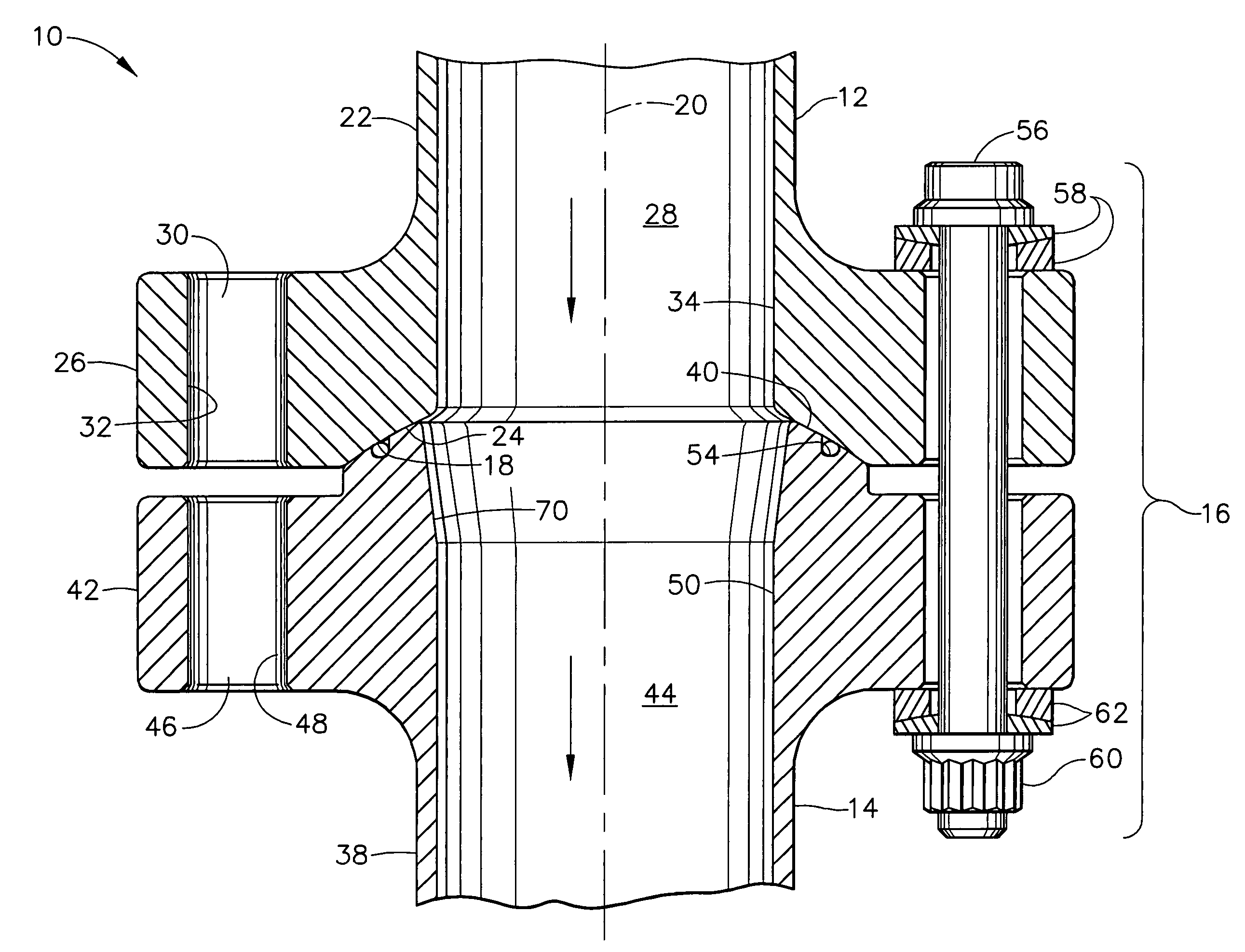
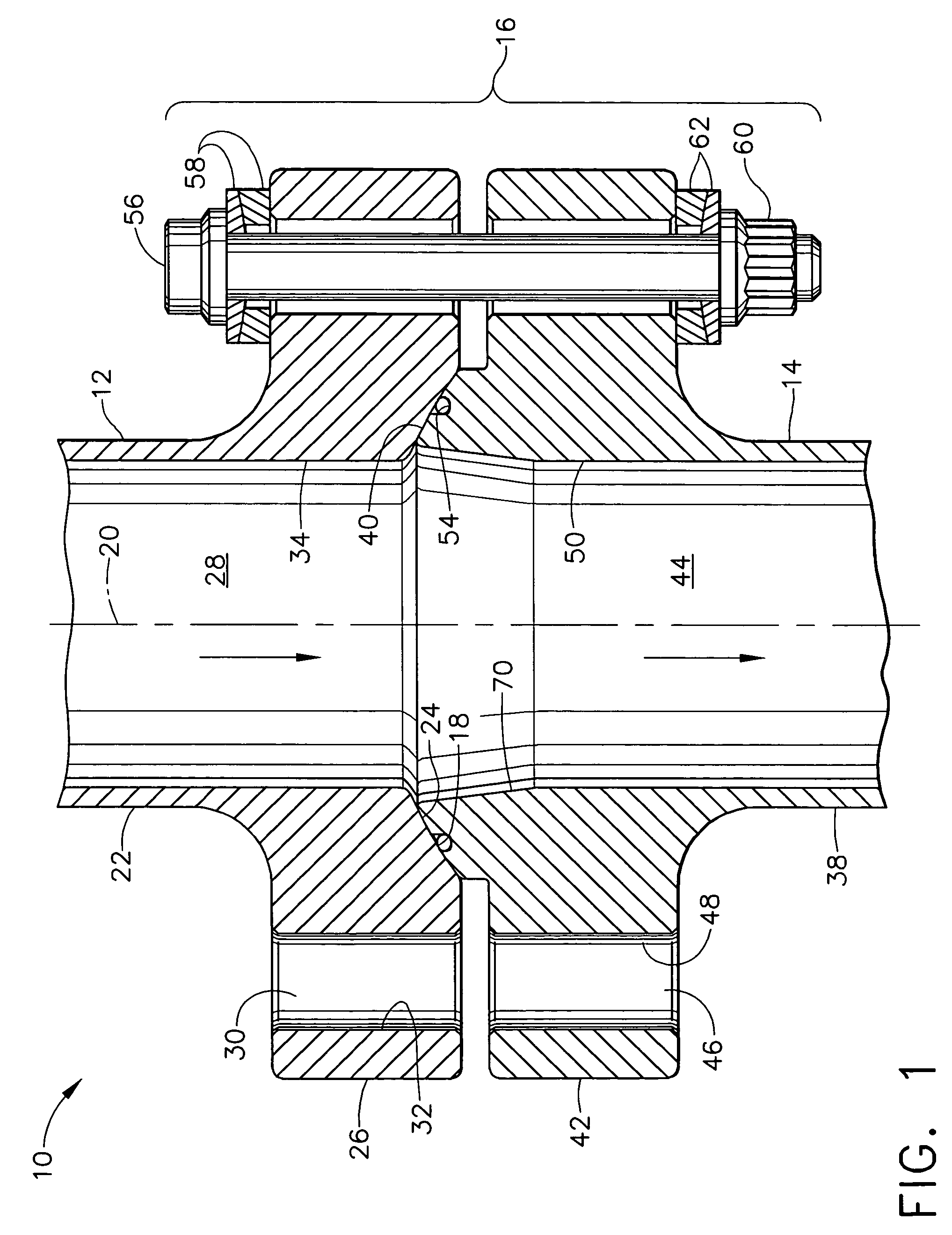
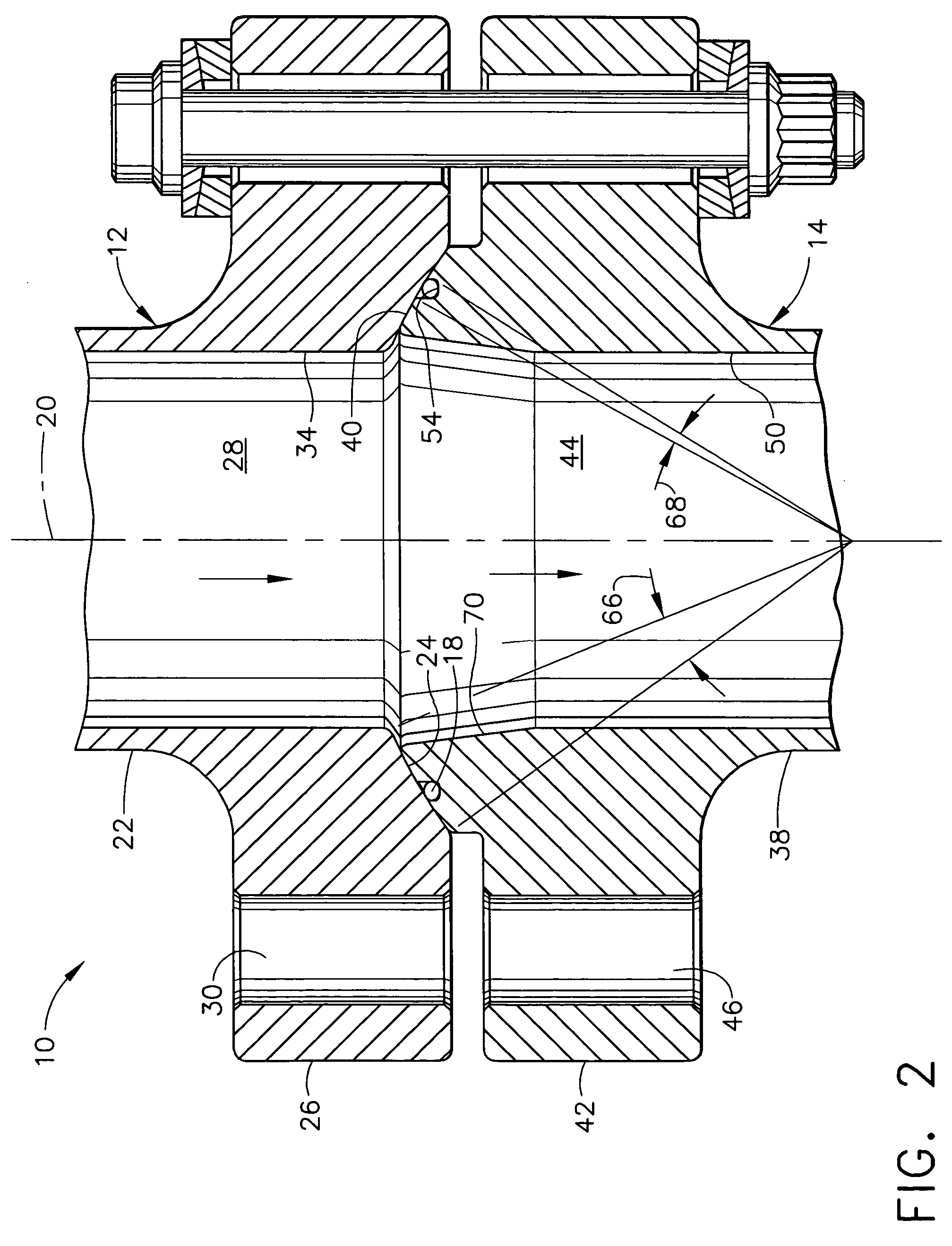
[0019]Due to the inherent tolerance variability of hardware, flange misalignments can occur during the installation of mating components for a liquid-propellant rocket engine. Further, these flange misalignments can include axial, lateral and / or angular offsets. If these misalignments are high, they can import significant loads into the two mating components, which can lead to failure. To address this flange misalignment issue, a spherical flange assembly was developed that allows for misalignment yet reduces imparted loads, while at the same time provides sufficient sealing against leakage. The design of the present invention was tested to evaluate and compare performance parameters, such as, for example, misalignment and leakage. During the testing, the environmental conditions ranged from −100 to +400 degrees Fahrenheit (° F.), with 1000 to 6000 pounds per square inch (psi) pressure being applied to the spherical flange assembly.

[0020]Referring to the Figures, and in particular F...


PUM


Abstract

A spherical flange assembly is disclosed. The spherical flange assembly comprises a seat member, a heel member, a seal gland and at least one nut and bold assembly. The seat member includes a concave portion. The heel member includes a convex portion and a seal gland opening. The seal gland is disposed within the seal gland opening.

Description

FIELD OF THE INVENTION[0001]The present invention is directed to spherical flange assemblies and, in particular, to spherical flange assemblies that allow for angular misalignment without resulting in either large duct loads or joint leakage.BACKGROUND OF THE INVENTION[0002]Currently, aircraft designers and manufacturers use various flexible, joints throughout the manufacture of the jet engines for use in the aircraft. To this end, various attempts to develop a satisfactory flexible, moderately pressurized joint have been made.[0003]For example, U.S. Pat. No. 4,448,449, issued to Halling, et al. and entitled “Flexible Piping Joint and Method of Forming Same” (Halling), discloses a fluid-tight coupling and sealing apparatus. Hailing describes a flexible piping joint, for use in fluid systems at moderate pressures and temperatures, that require a limited amount of angulation during operation. The invention in Halling, however, employs structurally inefficient load paths and non-metall...

Claims


Application Information

Patent Timeline
Patent Type & Authority Patents(United States)
IPC IPC(8): F16L19/00F16L27/00F16L27/10
CPCF16L27/1012
Inventor STANGELAND, MAYNARDURQUIDI, RONALD
Owner AEROJET ROCKETDYNE OF DE
Why Eureka
Try Eureka