Pneumatic conveyor device and method

Inactive Publication Date: 2006-12-05
CLAUDIUS PETERS PROJECTS
View PDF22 Cites 56 Cited by
  • Summary
  • Abstract
  • Description
  • Claims
  • Application Information

AI Technical Summary

Benefits of technology

[0007]Proceeding from a conveying device according to U.S. Pat. No. 2,919,159, the object on which the invention

Problems solved by technology

Pneumatic conveying devices present difficulties particularly at those points where the bulk material to be conveyed occurs in a high concentration, for example at the feed point.
Providing the propellant gas stream with an appropriately high velocity is complicated, specifically both in structural terms, particularly with regard to the size of the pressure generator and filter required, and from cost standpoints, particularly with regard to the energy outlay required.
This has, however, the serious disadvantage that the bulk material cannot be conveyed in any desired direction, but only ever downward.
This conveying device has a disadvantage that the entire conveying trough has to be provided with flui

Method used


Image

  • Pneumatic conveyor device and method
  • Pneumatic conveyor device and method
  • Pneumatic conveyor device and method

Examples


Embodiment Construction

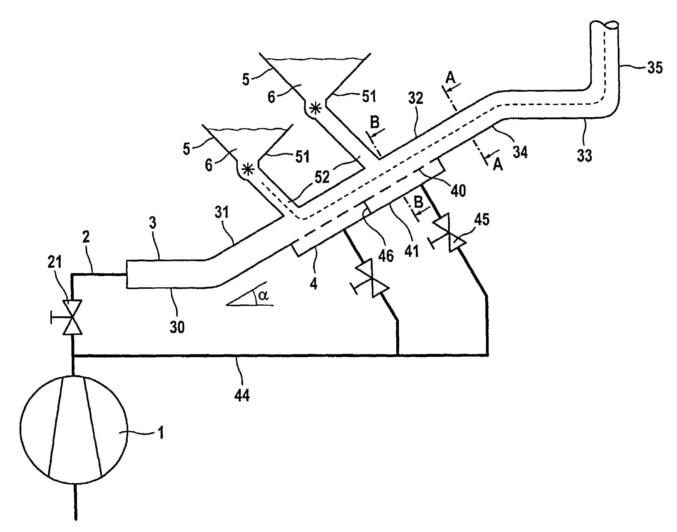
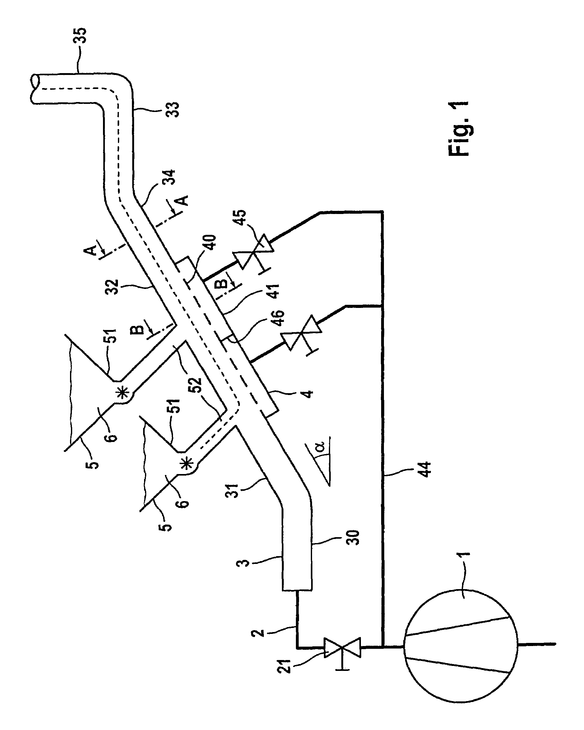
[0034]A pneumatic device is illustrated in the exemplary embodiment according to FIG. 1. It consists of an elongate conveying pipe 3, at the start of which is connected a supply line 2, through which propellant gas under excess pressure is blown into the conveying pipe 3 by a blower 1. To regulate the supply of propellant gas, an adjusting valve 21 is arranged in the supply line 2.

[0035]The conveying pipe 3, only part of which is illustrated, has a plurality of portions 30 to 35. In its first portion 30, it runs horizontally, while the portions 31 to 34 run at an inclination upward by the amount of an elevation angle a. The portion 34 is followed by a portion 35 running vertically upward; the further run of the conveying pipe 3 is not illustrated. The conveying pipe is given the reference symbol 33.

[0036]Two bulk material feed means 5 are provided for supplying the bulk material. These may be containers which have a funnel-like shape at their lower end 51. The tip of this funnel-lik...


PUM


Abstract

The invention relates to a device for the pneumatic conveyance of bulk material, including a conveying pipe which defines a conveying path for the bulk material and in portions has a fluidizing pipe segment and a propellant gas source which is connected to the conveying pipe and is designed for the supply of propellant gas in the direction of the conveying path. The conveying pipe is provided with a fluidizing pipe segment at least in the region of a bulk material feed means and, if appropriate, also at further critical portions of the conveying pipe, in particular upstream of deflection points. As a result, the bulk material, which is often encountered there in a high concentration, can be fluidized, with the result that it can be conveyed, with low friction, at relatively low gas velocities. The invention relates, furthermore, to a corresponding conveying method.

Description

FIELD AND BACKGROUND OF THE INVENTION[0001]The invention relates to a device for the pneumatic conveyance of bulk material, with a conveying pipe which defines any desired conveying path for the bulk material, and with a propellant gas source which is connected to the conveying pipe and is designed for the supply of propellant gas in the direction of the conveying path, and to a corresponding method.[0002]For the conveyance of granular or pulverulent material (bulk material), pneumatic conveying devices are known from prior public use. At a feed point, the bulk material to be conveyed is supplied to the conveying device, by which it is then transported by means of a gas stream in a conveying pipeline to a discharge point. This gas stream (propellant gas) may be generated by suction or by pressure; either a suction or a pneumatic pressure conveying device is referred to. These pneumatic conveying devices make it possible to transport the bulk material along virtually any desired path...

Claims


Application Information

Patent Timeline
IPC IPC(8): B65G53/04B65G53/20B65G53/52
CPCB65G53/20B65G53/521
Inventor HILGRAF, PETER
Owner CLAUDIUS PETERS PROJECTS
Why Eureka
Try Eureka