String pulling head structure of a racket stringer

a stringer and head technology, applied in the field of stringer head structure of racket stringer, can solve the problems of affecting the performance of the stringer, and affecting the quality of the stringer, so as to reduce the cost of the material, speed up the processing speed, and quickly form the slots

Inactive Publication Date: 2006-12-05
VAN DER POLS ERIK BERNARD
View PDF4 Cites 7 Cited by
  • Summary
  • Abstract
  • Description
  • Claims
  • Application Information

AI Technical Summary

Benefits of technology

[0004]It is therefore a primary object of the present invention to provide a string pulling head structure of a racket stringer, including a first string chuck and a second string chuck and a first chucking plate and a second chucking plate. Each of the opposite faces of the string chucks and the chucking plates is formed with several slots. An antiwear slat is obliquely disposed on the bottom of each of the slots, whereby the bottom of the slot is inclined. Multiple ball members are disposed in each slot to frictionally abut against the antiwear slat. Therefore, the string chucks and the chucking plates can be made of aluminum or engineering plastic to lower the cost for the material. Moreover, when processing the string chucks and the chucking plates, an ordinary milling cutter can be used instead of the conventional spherical milling cutter to quickly form the slots without considering the slope of the bottom of the slot. Therefore, the processing can be speeded and thus the manufacturing time and cost are greatly reduced.

Problems solved by technology

Otherwise, the spherical milling cutter will be damaged.
Therefore, it will take about one hour for processing.
In addition, it is quite hard to keep good quality of the channels 77 in processing.
Accordingly, it is time-consuming to manufacture the string pulling head and the manufacturing cost is high.

Method used


Image

  • String pulling head structure of a racket stringer
  • String pulling head structure of a racket stringer
  • String pulling head structure of a racket stringer

Examples


Embodiment Construction

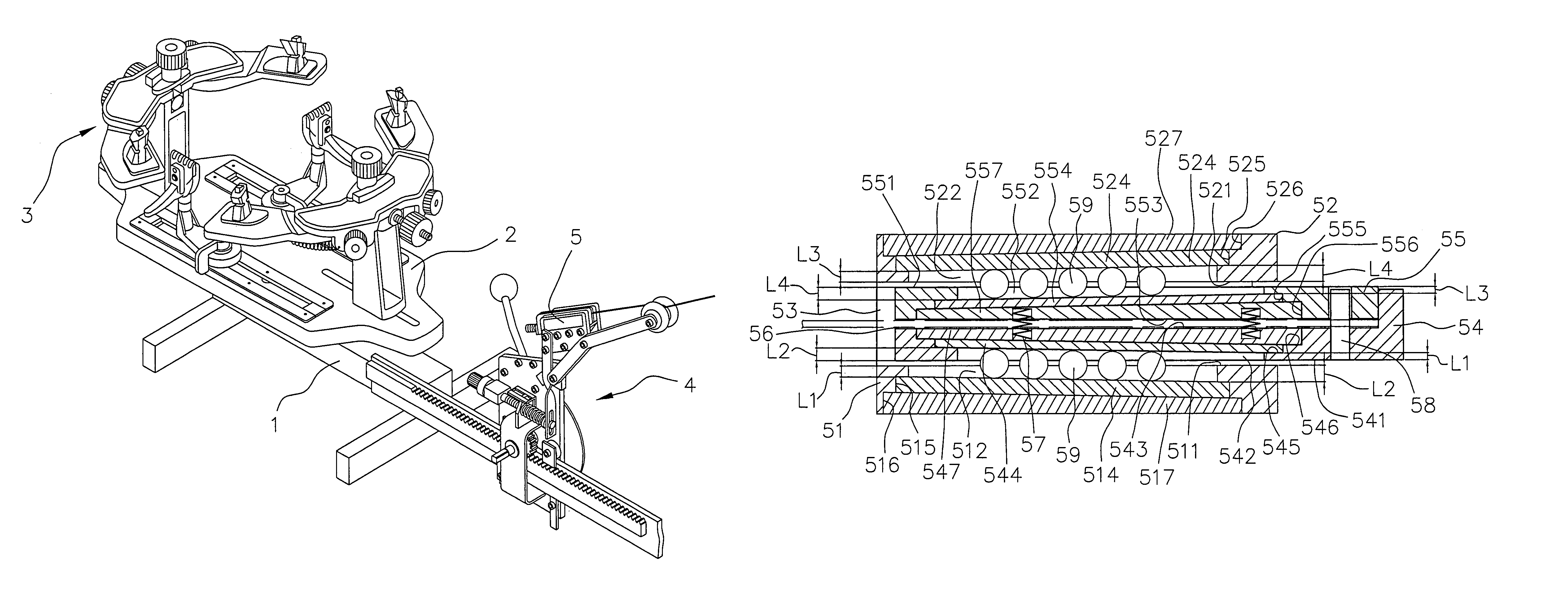
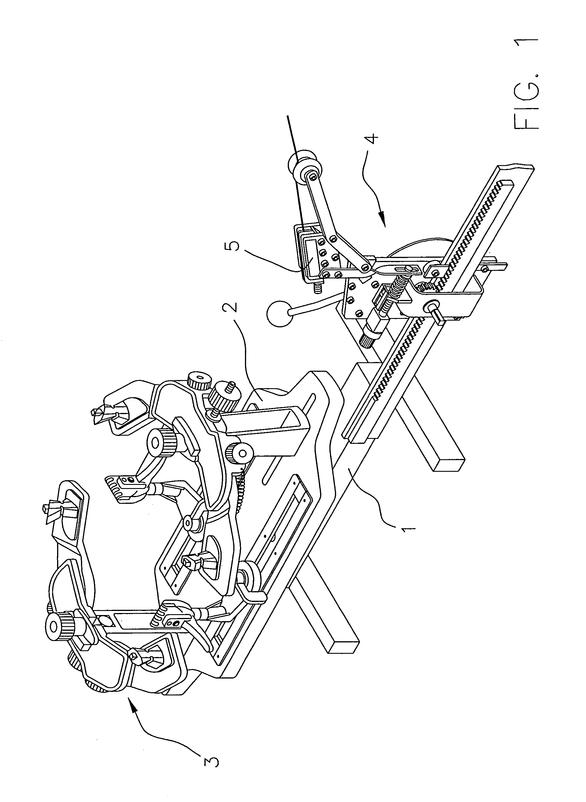
[0018]Please refer to FIG. 1. The racket stringer of the present invention includes a base seat 1 and a rotary bench 2 disposed on the base seat 1. A ratchet fixing device 3 is arranged on the rotary bench 2 for fixing a racket. A string chucking device 4 is mounted on the base seat 1 on one side of the rotary bench 2 for pulling the string. A string pulling head structure 5 is disposed at top end of the string chucking device 4 for chucking the string.

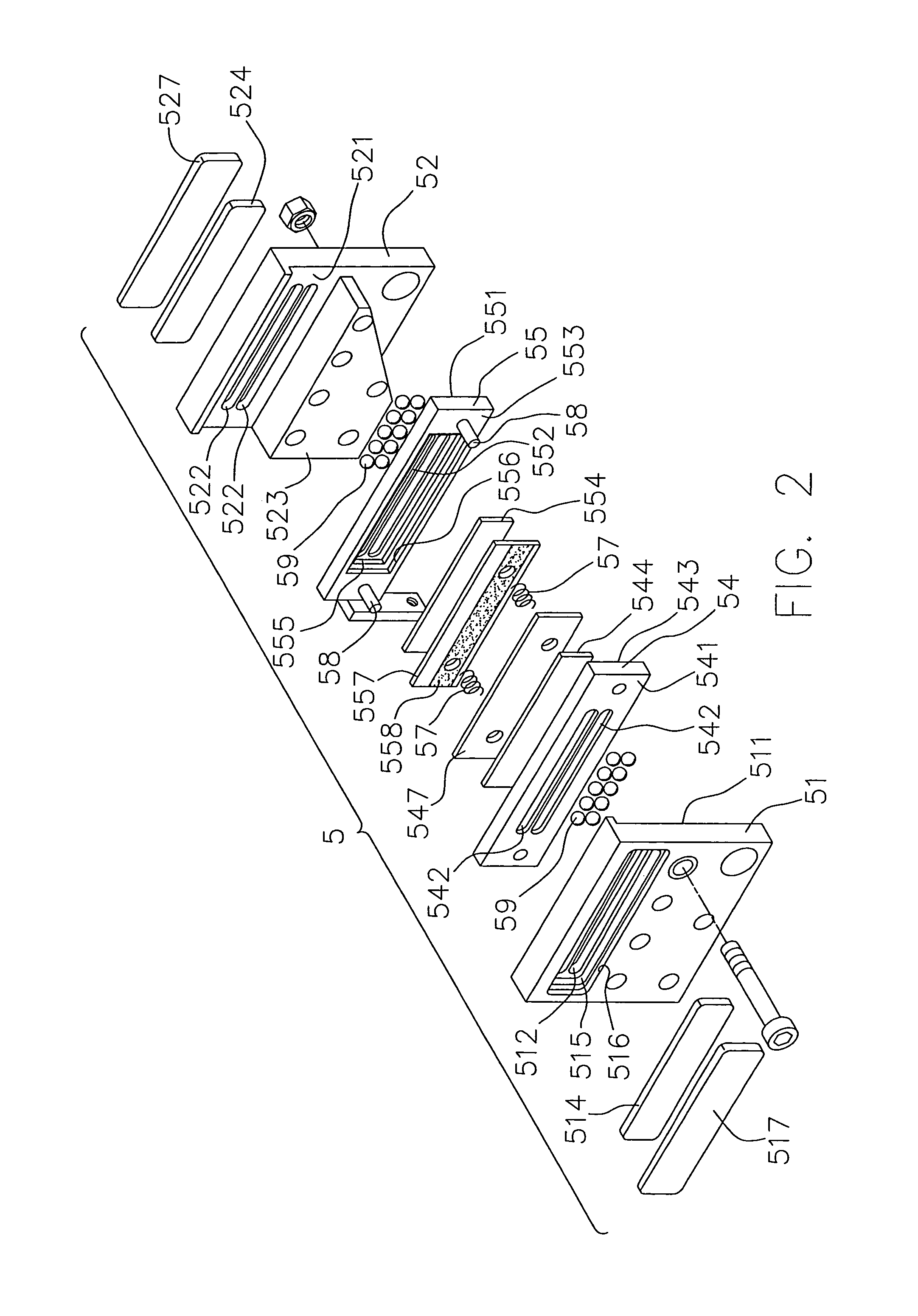
[0019]Referring to FIGS. 2 and 3, the string pulling head structure 5 includes a first string chuck 51 and a second string chuck 52 fixed with each other by screws. A projecting block 523 extends from a lower section of the second string chuck 52 toward the first string chuck 51. Accordingly, a slide way 53 is defined between opposite inner faces 511, 521 of upper sections of the first and second string chucks 51, 52. A first chucking plate 54 and a second chucking plate 55 are disposed in the slide way 53. The outer faces 541, 551 of...


PUM


Abstract

A string pulling head structure of a racket stringer, including a first string chuck and a second string chuck fixed with each other and a first chucking plate and a second chucking plate disposed between the first and second string chucks. Each of the opposite faces of the first and second string chucks and the first and second chucking plates is formed with two parallel slots. An antiwear slat is disposed on one side of each of the slots to serve as the bottom of the slot. The slats are inclined by equal inclination angle but in reverse direction, whereby the depths of two ends of the slots are unequal to each other.

Description

BACKGROUND OF THE INVENTION[0001]The present invention is related to a string pulling head structure of a racket stringer. Each of the opposite faces of the string chucks and the chucking plates is formed with two parallel slots. An antiwear slat is disposed on one side of each of the slots to serve as the bottom of the slot. The slats are inclined by equal inclination angle but in reverse direction. The string pulling head structure can be made at lower cost.[0002]FIGS. 5 and 6 show a string pulling head structure of a conventional racket stringer. The string pulling head structure includes a string pulling head 7 composed of a first string chuck 71 and a second string chuck 72 mated with each other and fixed with each other by screws. A first chucking plate 73 and a second chucking plate 74 defining therebetween a chucking space 75. Springs 76 are compressed between the first and second chucking plates 73, 74 for pushing the first and second chucking plates 73, 74 to respectively ...

Claims


Application Information

Patent Timeline
Patent Type & Authority Patents(United States)
IPC IPC(8): A63B51/14
CPCA63B51/14
Inventor VAN DER POLS, ERIK BERNARD
Owner VAN DER POLS ERIK BERNARD
Why Eureka
Try Eureka