Shock sensor system and method

a sensor system and shock sensor technology, applied in the direction of acceleration measurement, speed/acceleration/shock instrument details, instruments, etc., can solve the problems of time and expense related to field calibration, the need for field calibration brings with it concomitant expense, and the inability to discuss the details of the sensor housing assembly or the uniformity of its response, etc., to achieve the effect of enhancing mechanical energy transfer, reducing field calibration of the sensor configuration, and reducing the cost of field calibration

Active Publication Date: 2011-11-08
ESSENCE SECURITY INTERNATIOAL LTD
View PDF14 Cites 10 Cited by
  • Summary
  • Abstract
  • Description
  • Claims
  • Application Information

AI Technical Summary

Benefits of technology

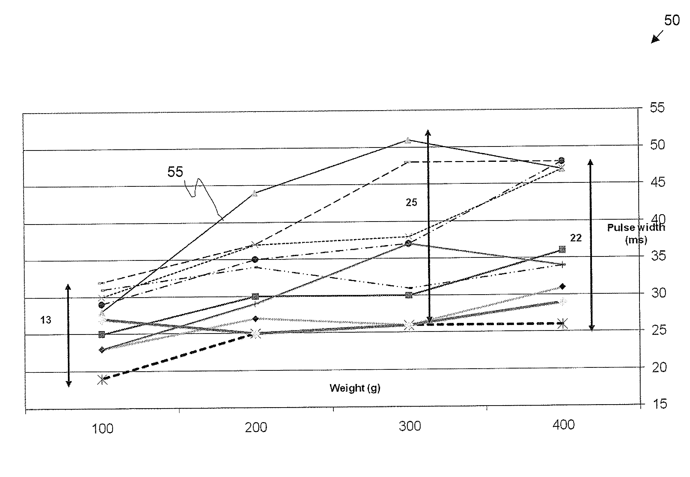
[0010]According to the teachings of the present invention there is provided, a surface-mountable shock sensor configuration having substantially eliminated field calibration, comprising: housing assembly; and a shock sensor replaceably mountable within the housing assembly, wherein the shock sensor configuration yields a repeatable shock response for a plurality of shock sensors, in response to shocks applied to a surface upon which the sensor configuration is mounted. Preferably, the sensor configuration has a top and a bottom cover. Most preferably, the sensor configuration is made from a low cost material. Typically, the surface-mountable shock sensor configuration includes an internal a clip, the clip acting to securely retain the shock sensor within the housing. Most typically, the clip includes a protuberance designed to enhance the transference of mechanical energy from the sensor configuration to the shock sensor.
[0012]According to the teachings of the present invention there is further provided a method of obtaining a repeatable shock response for a plurality of shock sensors, in response to shocks applied to a surface upon which a sensor configuration is mounted, comprising the steps of: taking a housing assembly; and mounting a replaceable shock sensor within the housing assembly, thereby substantially eliminating field calibration of the sensor configuration. Preferably, the sensor configuration has a top and a bottom cover. Most preferably, the sensor configuration is made from a low cost material. Typically, an internal clip is configured internal to the sensor configuration, the clip acting to securely retain the shock sensor within the housing. Most typically, a protuberance is formed on the internal clip, the protuberance designed to enhance the transference of mechanical energy from the sensor configuration to the shock sensor. Preferably the repeatable shock response is determined from a pulse width range of the shock sensors. Most preferably, the protuberance yields a substantially reduced pulse width range compared to the pulse width range of shock sensor configurations without the protuberance.

Problems solved by technology

However, there is no discussion of details of the sensor housing assembly or of uniformity of its response to shocks.
The need for field calibrations brings with it concomitant expense, as such calibrations must be performed by individuals having a certain level of skill and attention.
Clearly, the time and expense related to field calibrations represents a significant cost component of an alarm system.

Method used


Image

  • Shock sensor system and method
  • Shock sensor system and method
  • Shock sensor system and method

Examples


Embodiment Construction

[0018]The present invention includes a shock sensor system and method, and in particular, it concerns a shock sensor configuration that enjoys significant reduction or elimination of installation and other field calibrations.

[0019]In the specification and claims which follow, the term “shock sensor housing” is meant to mean the housing, typically fabricated from plastic or other lower cost materials, which supports and protects the shock sensor and its associated electronic circuitry. The shock sensor electronic circuitry is usually in the form of a printed circuit board (PCB), upon which a shock sensor is typically mounted, as known in the art.

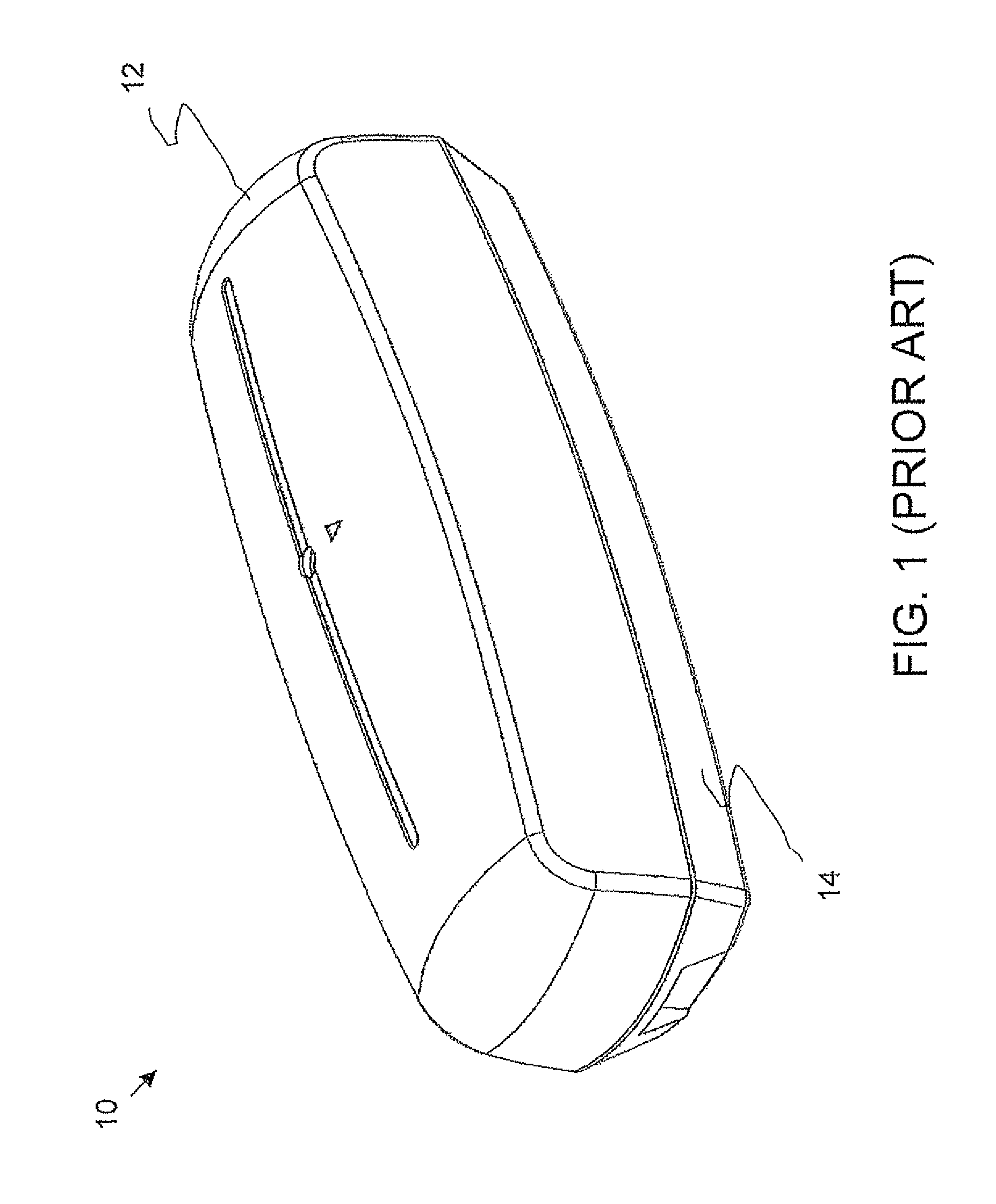
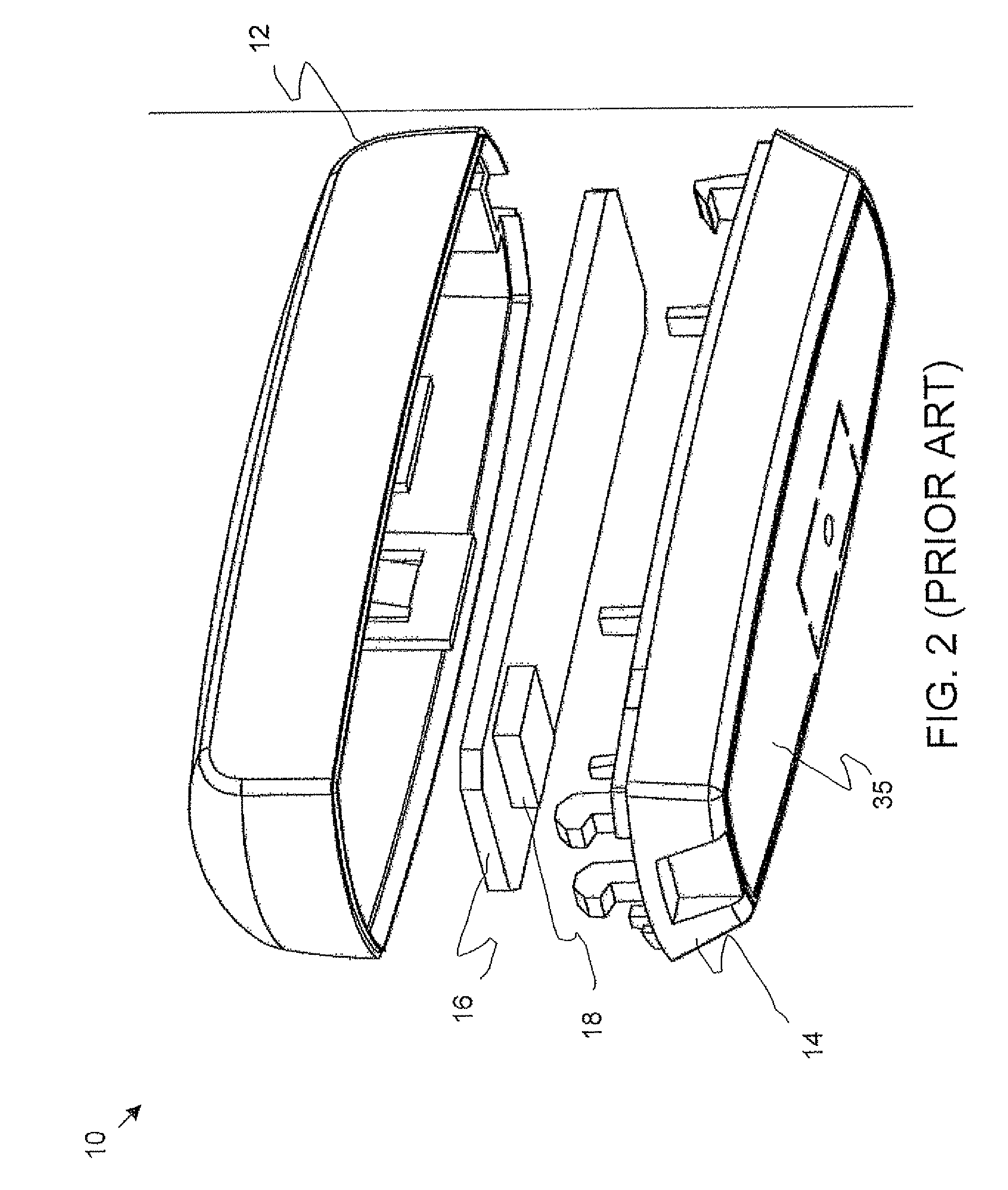
[0020]Reference is now made to FIGS. 1 to 4, which are pictorial representations of a shock sensor housing 10, as known in the art. Shock sensor housing 10, in the exemplary figures, comprises an upper cover 12, a base 14, and a PCB 16, upon which is mounted shock sensor 18. The PCB typically has a number of electronic components mounted upon...


PUM

PropertyMeasurementUnit
weightsaaaaaaaaaa
weightsaaaaaaaaaa
weightsaaaaaaaaaa

Abstract

A surface-mountable shock sensor configuration having substantially eliminated field calibration, comprising: a housing assembly; and a shock sensor replaceably mountable within the housing assembly, wherein the shock sensor configuration yields a repeatable shock response for a plurality of shock sensors, in response to shocks applied to a surface upon which the sensor configuration is mounted.

Description

FIELD AND BACKGROUND OF THE INVENTION[0001]The present invention relates to a shock sensor system and method, and in particular, it concerns a shock sensor configuration that enjoys significant reduction or elimination of field calibrations.[0002]Shock sensors are used in many applications to monitor or detect shock forces imparted to an object that is fragile, under investigation, and / or of value. Additionally, shock sensors may be used to monitor security environments, such as glass surfaces, windows, and doors for example to indicate when a glass surface is tampered with or a shock is applied. Shock sensors as known in the art are frequently accelerometers utilizing sensing materials placed on a thin diaphragm with a proof mass attached to the diaphragm. Some of these devices also utilize materials having a piezoelectric effect. One frequent use of mechanical shock detection devices is in the field of indicator alarms. Such alarms include those for sensing movement, time, tempera...

Claims


Application Information

Patent Timeline
Patent Type & Authority Patents(United States)
IPC IPC(8): G01N3/02
CPCG01P1/023G01P15/00
Inventor AMIR, HAIM
Owner ESSENCE SECURITY INTERNATIOAL LTD
Why Eureka
Try Eureka