

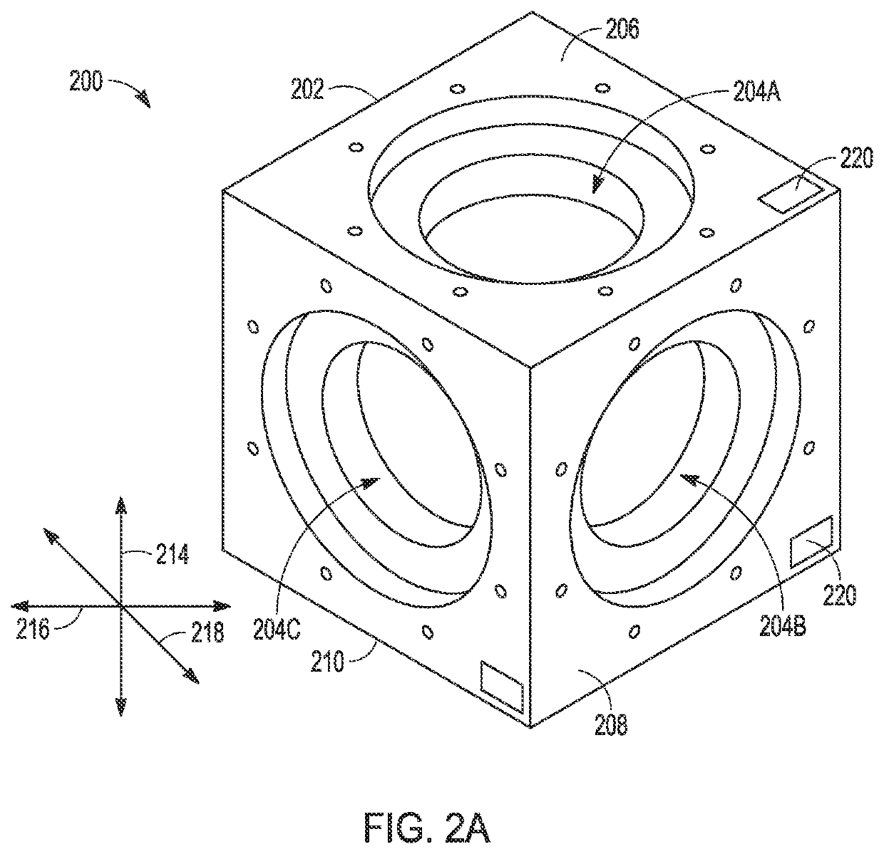
Multi-axis vibration test system with solid aluminum cube mounting fixture
a multi-axis, vibration testing technology, applied in vibration testing, structural/machine measurement, measurement devices, etc., can solve the problems of hydraulic shaker fundamental limitation and system limitation in frequency response, and achieve the effect of increasing surface area, increasing stiffness, and increasing surface area
- Summary
- Abstract
- Description
- Claims
- Application Information
AI Technical Summary
Benefits of technology
Problems solved by technology
Method used
Image

Examples
Embodiment Construction
[0025]Despite the existence of multi-axis vibration test systems, vibration testing is predominantly still performed using single axis systems. Despite early claims, the multi-axis vibration test systems have not delivered the required amplitude of linear displacement over the required frequency test bands in all three axes simultaneously and uniformly over the mounting surface(s). Although not desirable for testing of commercial devices, the lack of performance is particularly problematic and not acceptable for military grade devices subject to military standards (MIL-STD).
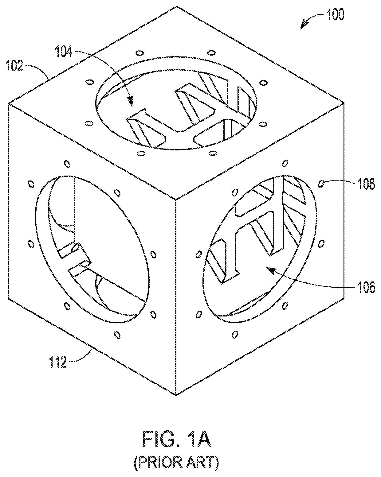
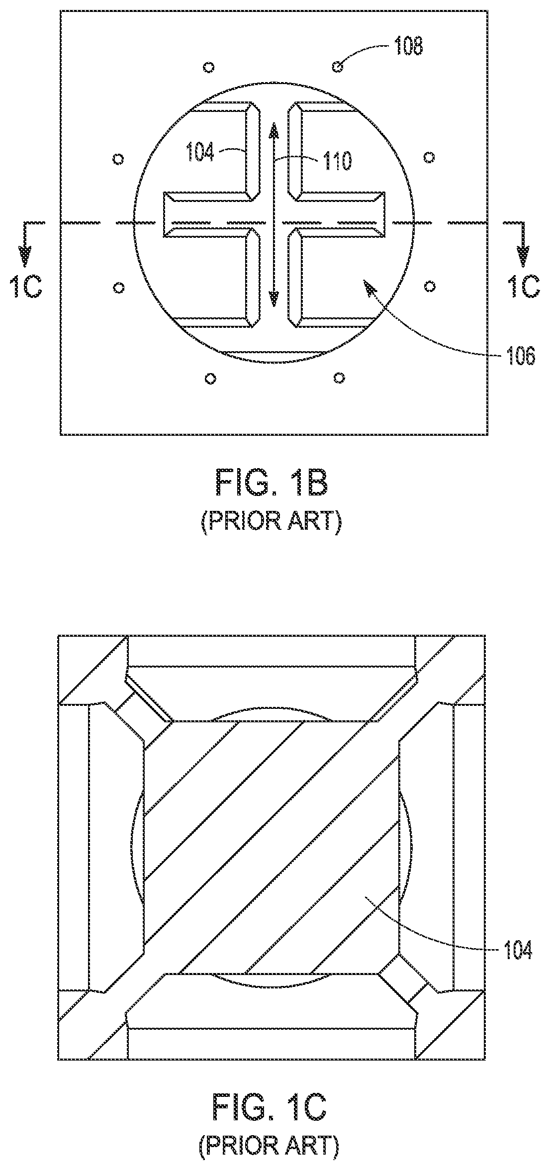
[0026]A typical 1-axis system includes a shaker and a mounting fixture on which to mount a device-under-test (DUT). A vibration fixture may be designed and used to mount the specific DUT to the mounting fixture. Three-axis testing may be performed with a couple of different configurations. In one configuration, the mounting fixture is a small (12″ or less) solid cube of Aluminum alloy or Magnesium, with Magnesium...
PUM
 Abstract
Description
Claims
Application Information