Electronic balance

a technology of electronic balance and electronic balance, applied in the field of electronic balance, can solve problems such as measurement error, and achieve the effect of enhancing measurement accuracy

Inactive Publication Date: 2006-12-05
SHIMADZU CORP
View PDF14 Cites 16 Cited by
  • Summary
  • Abstract
  • Description
  • Claims
  • Application Information

AI Technical Summary

Benefits of technology

[0009]This invention has been accomplished in view of such circumstances. An object of this invention is to provide an electronic balance having high accuracy and capable of weighing by eliminating the temperature difference between a weighing chamber and a balance body.
[0016]Since the electronic balance according to this invention is constructed as described above, measurement can be performed with no buoyancy difference between the measuring object and the calibration weight, thereby enhancing measurement accuracy.

Problems solved by technology

In an electronic balance having high accuracy permitting a very fine minimum readout value, high resolution and automatic sensitivity calibrating function, influence of air convection and temperature change due to the wind from outside may cause an error.
Thus, a difference occurs between the buoyancy which a measuring object placed on the weighing pan 91 receives and that which the calibration weight receives, which results in an error in the measured value.

Method used


Image

  • Electronic balance
  • Electronic balance
  • Electronic balance

Examples


second embodiment

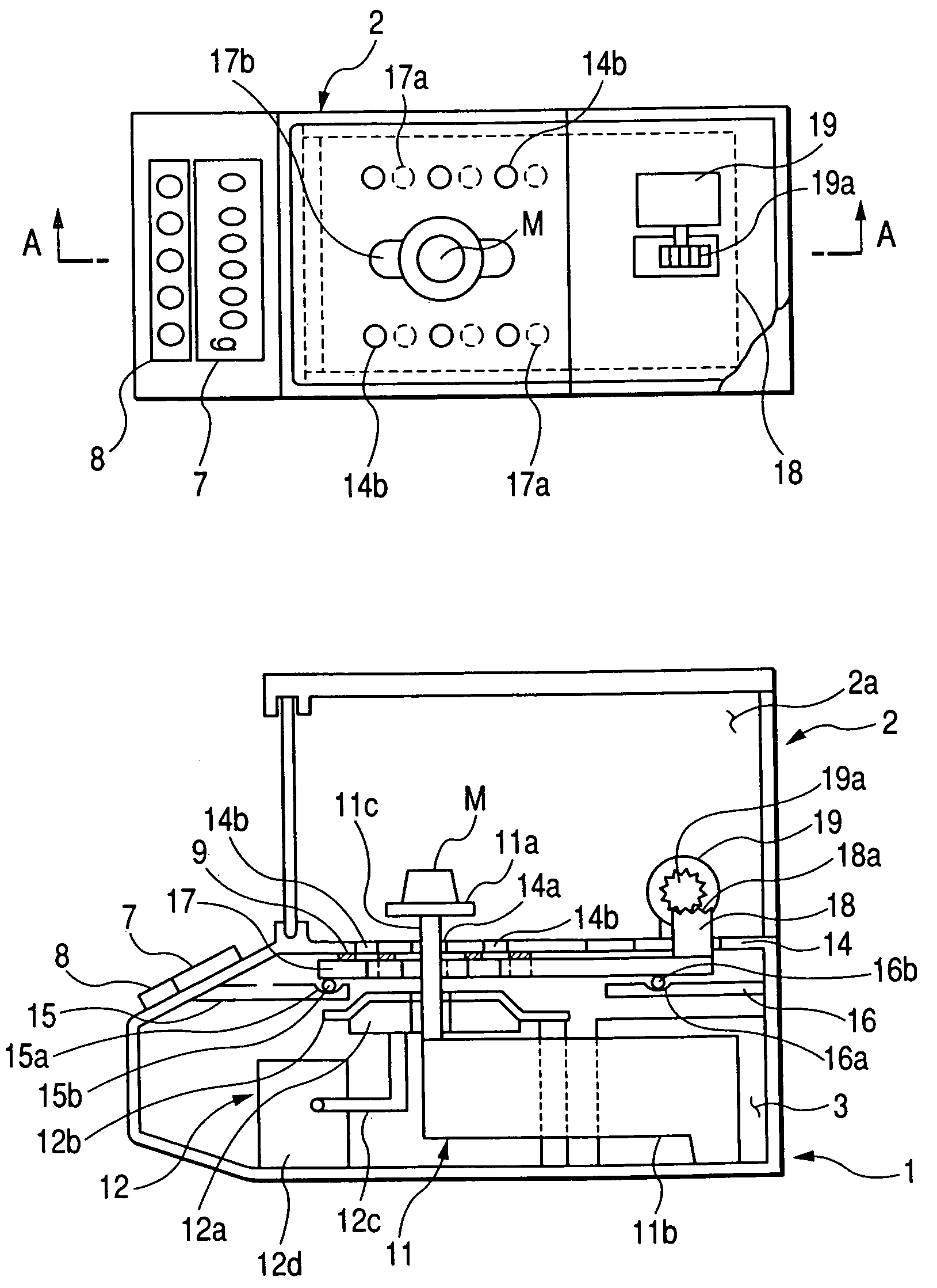
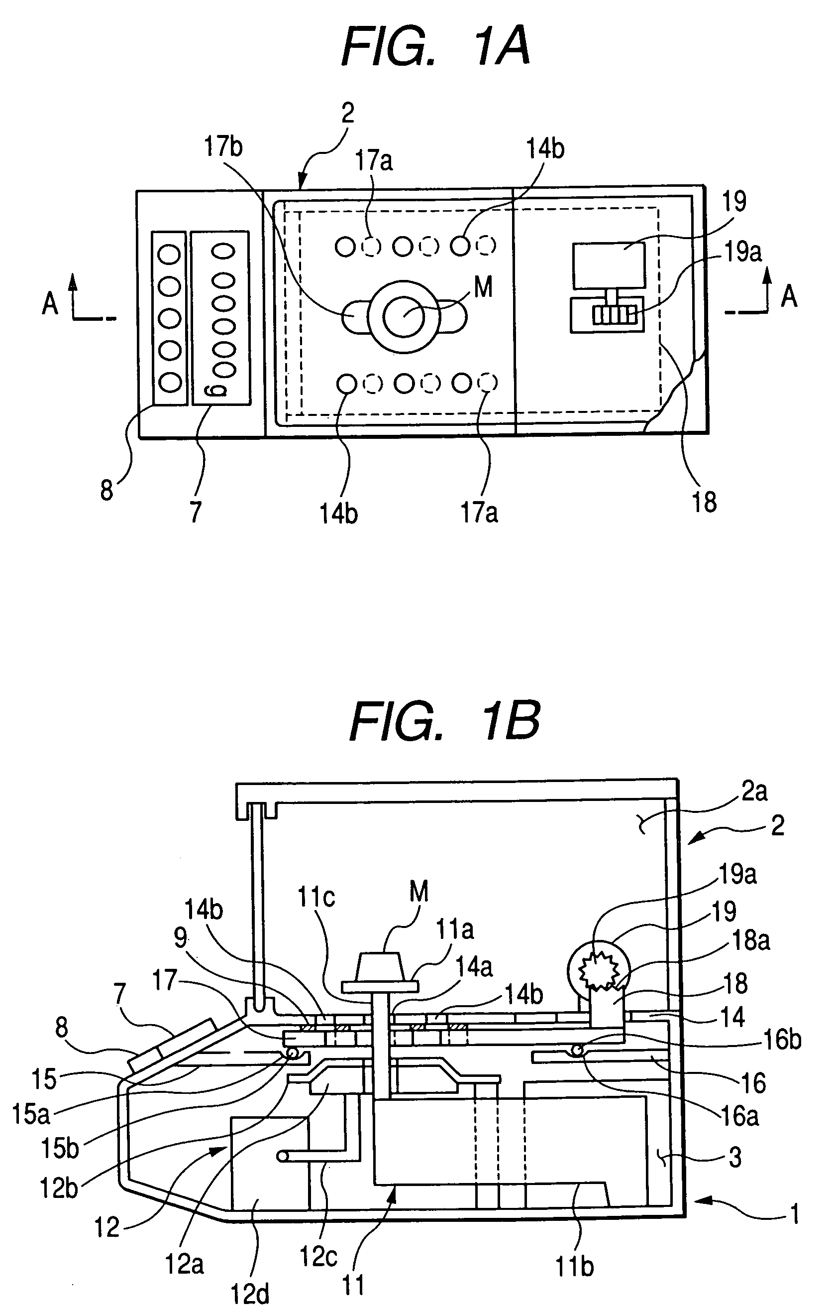
[0034]FIG. 3 is a flowchart showing the operation of an electronic balance according to the invention. In the electronic balance, when the temperature Tu measured by the temperature sensor 13a within the weighing chamber 2a is changed by a temperature equal to or higher than a predetermined temperature Tc, the indication “temperature change is large” is automatically displayed on the indicator 7. Simultaneously, the movable floor 17 is moved to the venting position where the vents 14b and the vents 17a align with each other. When the temperature Tu approaches the temperature Td within the balance body 1, the indication “temperature change is large” is erased and the movable floor 17 is moved to a non-venting position. Thus, accurate measurement can be performed with no difference in the buoyancy between the measuring object M and the incorporated weight 12a.

third embodiment

[0035]FIG. 4 is a flowchart showing the operation of an electronic balance according to the invention. In this electronic balance, when the temperature difference (Tu−Td) between the temperatures Tu and Td measured by the temperature sensors 13a and 13 is equal to or more than a predetermined value ΔTc, the indication “temperature difference is large” is automatically displayed on the indicator 7. Simultaneously, the movable floor 17 is moved to the venting position where the vents 14b and the vents 17a align with each other. When the temperature difference (Tu−Td) is smaller than ΔTc, the indication “temperature difference is large” is erased and the movable floor 17 is moved to the non-venting position. Thus, accurate measurement can be performed with no difference in the buoyancy between the measuring object M and the incorporated weight 12a.

fourth embodiment

[0036]FIG. 5 is a flowchart showing the operation of an electronic balance according to the invention. In this electronic balance, whenever a predetermined time elapses or a predetermined time elapses after sensitivity calibration is executed, the movable floor 17 is automatically moved to open / close the vents 14b.


PUM


Abstract

A floor portion separates a weighing chamber encircled by a windshield case and accommodating a weighing pan, and a balance body accommodating a load detecting section, an incorporated weight, etc. A plurality of vents is provided through the floor portion. A movable floor is arranged to be able to move back and forth on supporting members. A plurality of vents is provided through the movable floor on the rear side of the floor portion so that number and center position of the vents of the movable floor is the same as the vents of the floor portion. When a temperature difference between the temperatures within the weighing chamber and within the balance body is large, the movable floor is moved to permit airflow between the weighing chamber and the balance body.

Description

[0001]This application claims foreign priority based on Japanese Patent application No. 2004-222980, filed Jul. 30, 2004, the contents of which is incorporated herein by reference in its entirety.BACKGROUND OF THE INVENTION[0002]1. Field of the Invention[0003]This invention relates to an electronic balance equipped with a windshield case, and more particularly to an electronic balance having a high-resolution for eliminating a difference in a buoyancy between a weight for calibration incorporated in a balance body and a measuring object placed on a weighing pan within a weighing chamber.[0004]2. Description of the Related Art[0005]In an electronic balance having high accuracy permitting a very fine minimum readout value, high resolution and automatic sensitivity calibrating function, influence of air convection and temperature change due to the wind from outside may cause an error. In such an electronic balance, in order to remove the cause of an error, a method of encircling the pe...

Claims


Application Information

Patent Timeline
Patent Type & Authority Patents(United States)
IPC IPC(8): G01G21/28
CPCG01G21/286
Inventor IIDUKA, ATUSHISHIMAUCHI, KUNIO
Owner SHIMADZU CORP
Why Eureka
Try Eureka