
Thermal barrier for a thermistor

Active Publication Date: 2006-12-05
ROSEN TECH LLC
View PDF12 Cites 5 Cited by
  • Summary
  • Abstract
  • Description
  • Claims
  • Application Information

AI Technical Summary

Benefits of technology

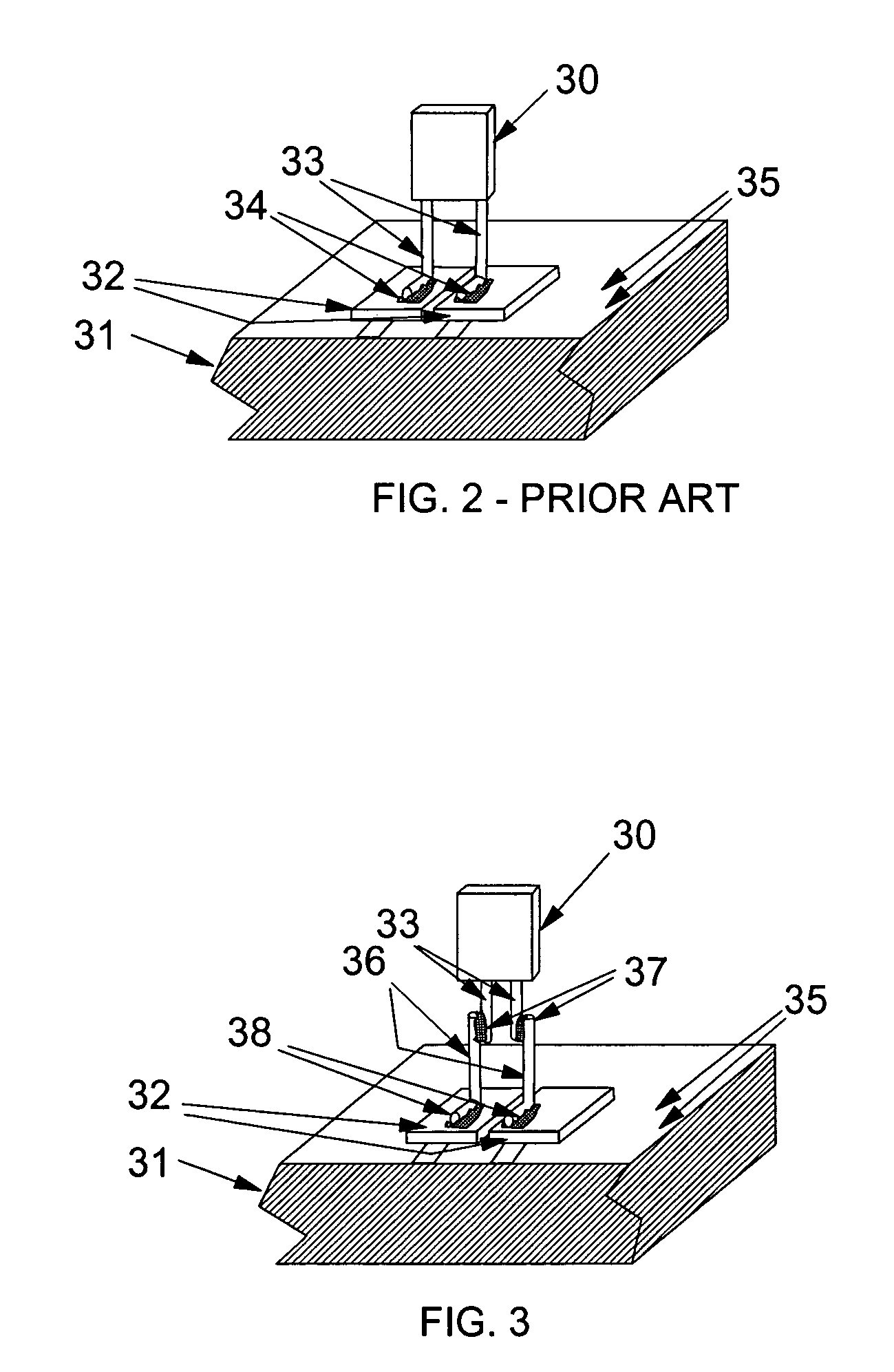
[0023]The invention further includes an effective thermal barrier between the thermistor and higher temperature solids or electrical components in a thermostat or its equivalent device. The invention thermal barrier substantially reduces or essentially eliminates undesired conductive heating of the thermistor from support means or other electrical components.

Problems solved by technology

Making thermostats with a small housing is desirable because they are usually prominently wall mounted and might be unsightly if too large.
However, increasing component density results in an increase in the density of energy that must be dissipated from the device as heat.
The more crowded thermostat housing will be unlikely to provide adequate ventilation to effectively remove this generated heat.
This causes the thermostat to operate environmental control equipment in error.
Air conditioning equipment operates too much and heating equipment operates not enough.
Limited techniques are available for dissipating heat from components in high-density component operation.
Further, heat sinks may absorb dissipated heat and increase the surface area over which that heat may be dissipated.
However, these techniques are of little value in a modern day thermostat.
Excessive cost and limited space for these components make them economically unavailable to reduce heat transfer to a thermistor locally mounted in a thermostat housing.

Method used


Image

  • Thermal barrier for a thermistor
  • Thermal barrier for a thermistor
  • Thermal barrier for a thermistor

Examples


Embodiment Construction

[0042]The invention is now discussed with reference to the figures.

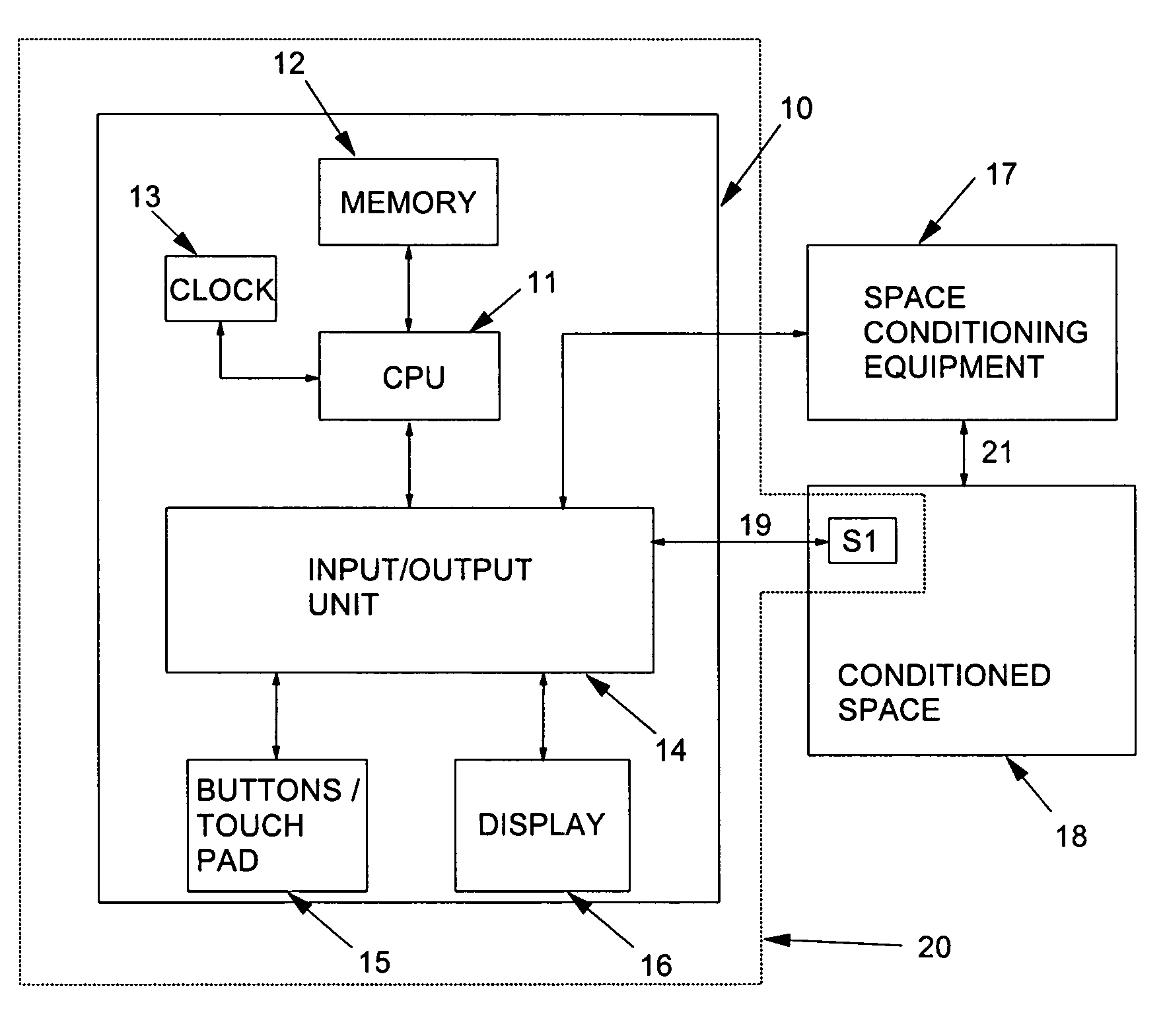
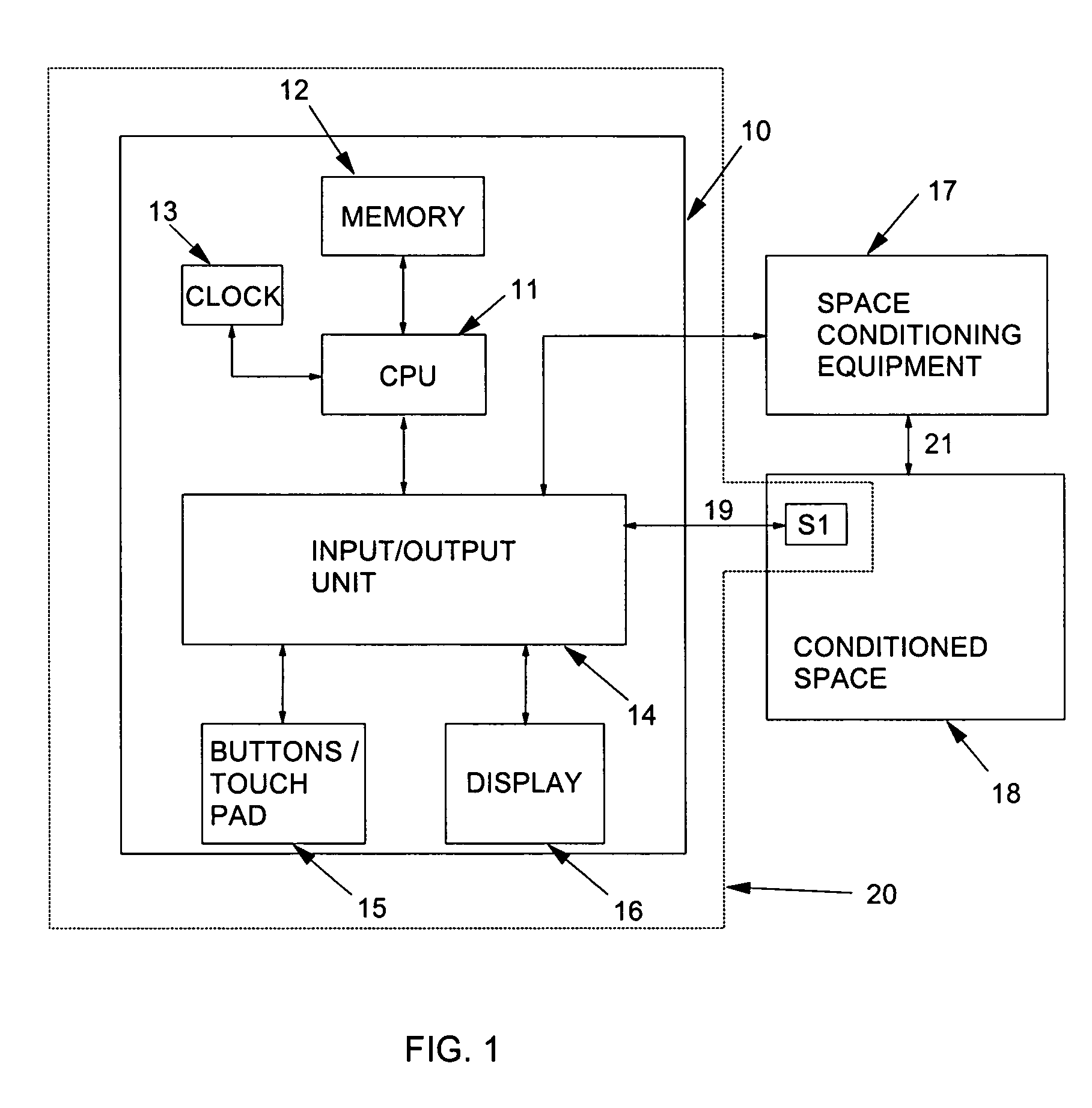
[0043]Referring now to FIG. 1, central control device 13 is shown in a block diagram form with a processor 10 connected to an environmental temperature sensor S1 which are disposed with access to conditioned space 18. The processor 10 and the sensors S1 are be situated in a common housing 20, so that sensor S1 has effective access to the room in which the housing 20 for processor 10 is located.

[0044]The processor 10 includes a central processing unit (CPU) 11 in communication with a memory 12 which stores data and program information and also, via an input / output unit (I / O unit) 14, an optional user interface 15 and a liquid crystal or other type display (LCD) 16. The memory 12 may include a read-only part which is factory-programmed and a random-access part which stores data subject to change during operation. A settable real time clock 13 is used to keep time in the central control device to facilitate diverse oper...


PUM


Abstract

The present invention is a an effective thermal barrier between the thermistor and higher temperature solids or electrical components in a thermostat or its equivalent device. The invention thermal barrier substantially reduces or essentially eliminates undesired conductive heating of the thermistor from support means or other electrical components.

Description

FIELD OF THE INVENTION[0001]This invention relates to the art of thermostats and, more particularly, to a thermostat incorporating an environmental temperature sensing device connected by conductor to local electrical circuits.BACKGROUND OF THE INVENTION[0002]Thermostats have been used for many years as a temperature sensitive switch which controls heating and / or cooling equipment for conditioning a space in which the thermostat, or a temperature sensor connected to the thermostat, is placed. In the well known manner, a simple thermostat can be adjusted to establish a temperature set point such that, when the sensed temperature in the conditioned space reaches the set point, the thermostat interacts with the heating and / or / cooling equipment to take suitable action to heat or cool the conditioned space as may be appropriate for the season.[0003]Modern thermostat systems, which take advantage of the ongoing rapid advances in electronic technology and circuit integration, have many fea...

Claims


Application Information

Patent Timeline
IPC IPC(8): H05B1/02
CPCH05K1/0201H05K3/3426H05K2201/062H05K2201/10022H05K2201/10909H05K2201/10916H05K2201/10962Y02P70/50
Inventor ROSEN, HOWARD
Owner ROSEN TECH LLC
Learn More