Optical window for monitoring samples

a sampling window and optical technology, applied in the field of optical sampling windows, can solve the problems of material stickyness, double the cost of the arrangement of the lens,

Inactive Publication Date: 2006-12-05
NORDSON CORP
View PDF17 Cites 41 Cited by
  • Summary
  • Abstract
  • Description
  • Claims
  • Application Information

AI Technical Summary

Problems solved by technology

Such an arrangement doubles the cost of the lenses.
One severe disadvantage that limits the use of infrared gauges in the monitoring of materials being dried in fluid bed and other dryers is that the material can be sticky, particularly when moist.
Since, in these circumstances, it is not possible to monitor the water content of the material being dried, the drying may have to be stopped in order to allow the window to be cleaned.

Method used


Image

  • Optical window for monitoring samples
  • Optical window for monitoring samples
  • Optical window for monitoring samples

Examples


Embodiment Construction

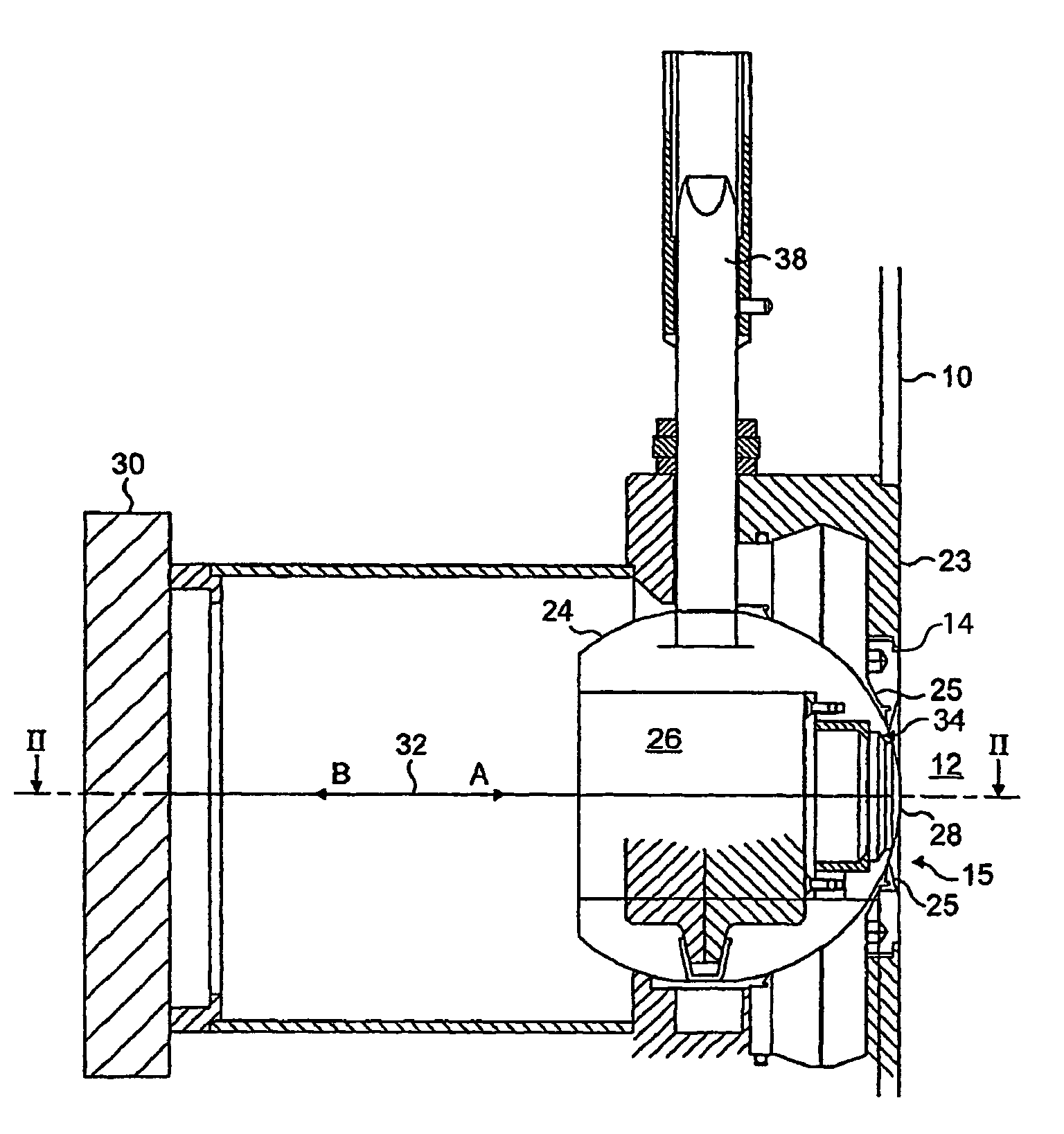
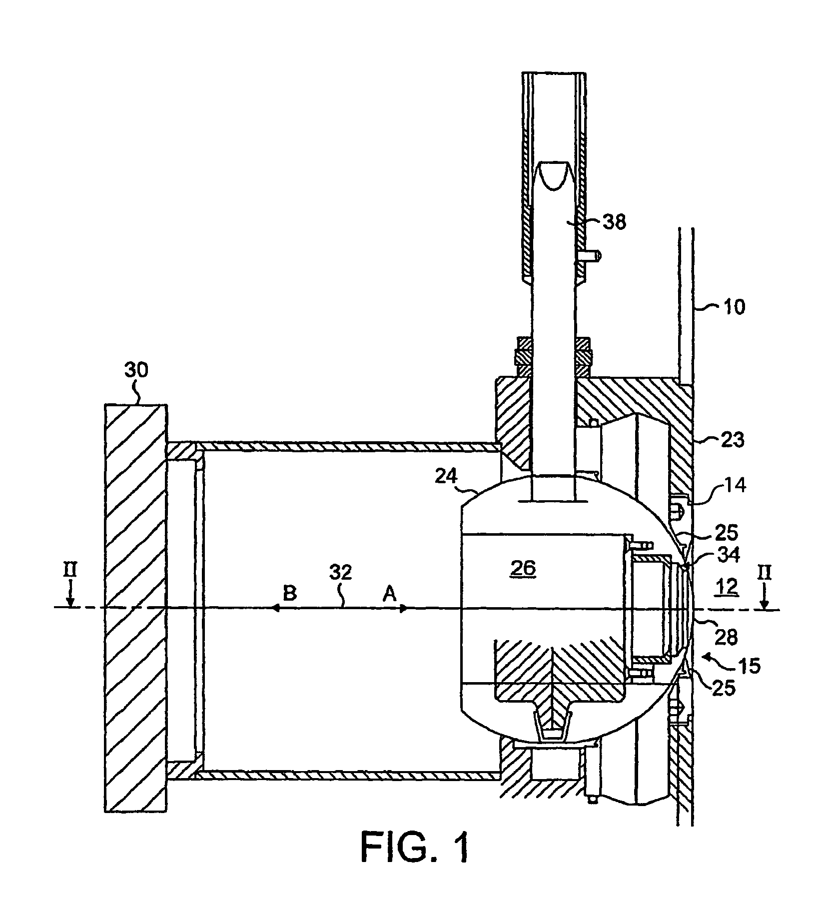
[0031]Referring initially to FIG. 1, there is shown the wall 10 of a dryer. Material to be dried is located in a drying compartment 12 (only part of the compartment is shown). The wall 10 has an opening 14 and an optical sampling window 15 according to the present invention extends across the opening. The window includes a socket 23 holding a sphere 24 containing a bore 26. The bore 26 is closed at one end by a radiation-transmitting element 28 which is located in contact with the dryer compartment 12, as shown in FIG. 1. PTFE seals 25 close the gaps between the spherical holder 24 and the wall 10.

[0032]An infrared spectrometer (“gauge”) is indicated schematically by block 30 and is located on the outside of the dryer compartment 12 on the axis 32 of the bore 26; the gauge can transmit infrared radiation in the direction of arrow A through the bore 26 and through the optical element 28 into the interior compartment 12 of the dryer. Likewise, radiation reflected by material within th...


PUM

PropertyMeasurementUnit
volatileaaaaaaaaaa
infrared wavelengthaaaaaaaaaa
optical measuring techniquesaaaaaaaaaa

Abstract

The invention is concerned with a material processing apparatus, e.g. a dryer such as a fluid bed dryer, for processing material, e.g. pharmaceuticals, in a compartment (12) having a wall (10). The wall has a window for transmitting radiation from an infrared spectrometer (30) into the dryer and for transmitting radiation from the material to the spectrometer. The spectrometer (30) can analyze the radiation transmitted from the material to measure a property of the material within the compartment, e.g. its moisture content. The radiation-transmitting element (28) is present in a moveable body (24), e.g. a sphere, that can be moved to bring the element (28) into a second position (31) in which the element is in contact with a duct (40) through which fluid can be passed to clean the element (28). In addition, a wiper member (34) may be provided that wipes the element (28) as it passes over it as the moveable body (26) is moved into the second position.

Description

CROSS REFERENCE TO RELATED APPLICATION[0001]The present application is the U.S. national stage application of International Application PCT / GB02 / 04195, filed Sep. 13, 2002, which international application was published on Mar. 27, 2003 as International Publication WO 03 / 025550. The International Application claims priority of British Patent Application 0122711.5, filed Sep. 20, 2001.TECHNICAL FIELD[0002]The present invention relates to optical sampling windows in apparatus for processing materials, e.g. dryers and granulators, and especially for use in monitoring material being processed using optical measuring techniques, for example infrared spectroscopy. As used in the present specification and claims, the terms “optical” and “radiation” are intended to refer to non-visible parts of the spectrum, for example infrared radiation, in addition to visible radiation.BACKGROUND ART[0003]Pharmaceuticals and other materials are often dried in fluid bed dryers and it is known to monitor th...

Claims


Application Information

Patent Timeline
Patent Type & Authority Patents(United States)
IPC IPC(8): G01J5/02G01N21/15G02B27/00
CPCG01N21/15G02B27/0006
Inventor BENSON, IAN BEETHOM
Owner NORDSON CORP
Why Eureka
Try Eureka